RF-31 I think my motor is wired incorrectly,take a look plz

I think, to get a true idea we need to see the other end at the reversing switch. I suspect there may be a wiring error but without seeing the switch I can't say for sure. To reverse the motor the factory is either swapping the red/yellow or the black/white
-Mark
The concern about the two bottom posts is unfounded- the posts are merely mounting points- the wire #s and colors match and that is all that matters.
So the motor is wired for 220/240. I believe the little breaker and incoming black wire are not used for 220/240 volt case and should be removed.
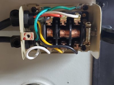
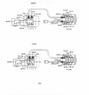
I posted a picture of the switch in attachments but ill link it again.yes the numbered wires run to the motor the others to the switch. thanks for help.20200511_173119.jpg20200510_032557_copy_2016x1512.jpg
 
Last edited:
First question is are the posts just posts or do they connect to something inside the motor? If they are just posts then I don't think that the reversing of the wires on the two bottom posts makes a difference. The red wire still goes to the #4 wire and the white wire still goes to the #6 wire. If the posts are connected to something inside the motor then you should change those two wires to conform to the diagram. You might want to do that anyway just to avoid confusion in the future.

And I agree with Mark that we need more info on the wiring of the reversing switch to know is something is amiss there.
Here is a picture of the switch and yes the wires run from the box inside the motor. To be precise the numbered wires run out of the engine into the box then the unnumbered wires run to the switch and the switch connects to power cord. here's some pics there's also more pics in the original post attachments. thanks for your help.20200510_012935.jpg20200511_173119.jpg
 

Attachments

  • 20200510_032557_copy_2016x1512.jpg
    20200510_032557_copy_2016x1512.jpg
    422.5 KB · Views: 20
Hey everyone if I'm not posting the pictures or attachments or writing in the most efficient way please forgive me im new to the whole forum thing at least the posting part. I really appreciate everyone's help and input, along with the time and thought everyone has invested into it. I am trying to also respond to threads that I can help with so I can give back to the forum and not just take. Also I am useing the search function to look for answers before posting. So again big thanks
 
Don't ever be afraid to ask questions on this forum. It is a very friendly forum and everybody shares whatever knowledge they have to help people out. Somebody always seems to have the answer to any question that is asked.

Welcome to the forum.
 
Do you have a wiring diagram for the drum switch? Post the wiring diagram if you have it or the model of the drum switch so we can find the wiring diagram online.
 
Pictures are fine, I believe you need to remove the little breaker and possibly make one minor wiring change for 220/240. I will post again tomorrow.
Ciao
 
Last edited:
Do you have a wiring diagram for the drum switch? Post the wiring diagram if you have it or the model of the drum switch so we can find the wiring diagram online.
The switch doesn't have a model or anything identifying except a YM logo on the cover. I found a diagram in a rf 31 manual online that looks to be the same as mine. At least the the switch wiring looks the same but the wiring diagram under the lid of the small box on my motor doesn't look the same as the one in the manual. Just the switch portion.
 

Attachments

  • 20200512_044537.jpg
    20200512_044537.jpg
    1.6 MB · Views: 32
  • Screenshot_20200512-064138_Drive.jpg
    Screenshot_20200512-064138_Drive.jpg
    197.2 KB · Views: 43
Aha that is the piece we needed. I was half-right, you still use the little breaker for 220/240 but you leave the red from the reversing switch unconnected. (wrap with tape)
Connect the breaker between black and 4.
2,3,5 connect together with nothing else connected on the post.
1 goes to white. Yellow goes to 6.
If the rotation of the motor is backwards with respect to the switch handle then swap yellow for red and leave yellow unconnected instead.
-Mark
PS apparently, according to the factory diagram the little breaker is not used for the 110/120 volt configuration- perhaps they ran out of post positions on the terminal block? Who knows? It would have been inserted between only one of the two run windings- either 1,2 or 3,4
 
Last edited:
Pictures are fine, I believe you need to remove the little breaker and possibly make one minor wiring change for 220/240. I will post again tomorrow.
Ciao
Im looking forward to hearing your thoughts on the wiring change. Thanks
Aha that is the piece we needed. I was half-right, you still use the little breaker for 220/240 but you leave the red from the reversing switch unconnected. (wrap with tape)
Connect the breaker between black and 4.
2,3,5 connect together with nothing else connected on the post.
1 goes to white. Yellow goes to 6.
If the rotation of the motor is backwards with respect to the switch handle then swap yellow for red and leave yellow unconnected instead.
-Mark
PS apparently, according to the factory diagram the little breaker is not used for the 110/120 volt configuration- perhaps they ran out of post positions on the terminal block? Who knows? It would have been inserted between only one of the two run windings- either 1,2 or 3,4
Mark I am confused at this point only due to the fact that there is a cover that closes off the box that houses these 6 posts.it has a diagram glued on it. Said diagram doesn't match the schematic I found online. I pulled that schematic because someone asked if I could find a diagram for the switch.it shows the drum switch that not only looks just like mine but happens to be currently wired the exact same way mine(switch) is.what do you think upon comparison. I feel nervous not following the diagram actually connected to my mill. I posted the diagram from my machine in the thumb nails I will also attach here to.1st pic is the diagram from my mill. 2nd is the schematic from online. Thanks for your help.20200510_032720.jpgScreenshot_20200512-064138_Drive.jpg
 
So I finished running 240v to my garage today.i followed the wiring diagram on the cover of the 6 post terminal box for 230v which ment switching the #6 and white to the bottom left post and the #4 and red to the bottom right post. I left the thermal reset button wired the way it was the top left and top right posts between #3,#5,#2 and black.I understand that isn't really changing the connections from what is was but I feel better that it matches the diagram. I left the switch wiring the same as it was before which matches the black and white schematic that I downloaded online and previously posted. The mill powers up fine and forward/reverse both work. Also now all 12 spinde speeds are working underload unlike before when I could only use the first 10 speeds. The motor is no longer getting hot. I feel like it was always wired correctly for 240v the reason that the previous owner had the bottom two posts wired up reverse from the diagram was because the wiring reached the terminal posts better that way. I am baffled as to why there was a 120v plug setup yet wired for 240v and he said he had been running on 120v.how he never ran into the overheating problem or not being able to use the 2 fasted spindle configurations is a wonder to me. Seems be working fine now. If anyone sees anything wrong with what I have done please let me know. And again thanks to everyone for all the help I truly appreciate everyone's time and consideration.
 
Back
Top