Rockford/Hedwick MV100 power table feed install

The spindle on my MV100 loosen up and created a bad fly cut surface finish, then started slinging oil. I removed the bottom spindle cover by taking out the 3 set screws and prying it off with 2 screwdrivers. Made a spanner to take the large nut off and dropped the spindle out.
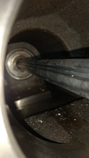
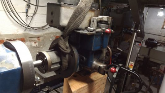
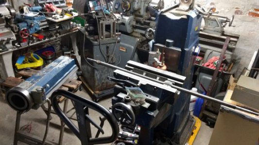
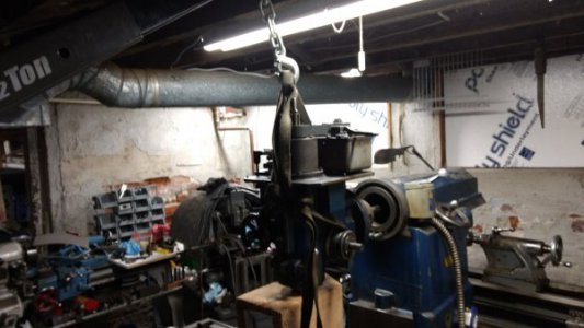
the nut in the center of the shaft was loose, that is what tightens the bearings against each other for the preload. I cleaned the bearings and took the spacer out and added a third bearing all with no seals, and installed an new bottom shaft seal. The spindle uses oil not grease if intended use is at high speeds. When rebuilding the spindle drill a vent hole at the top that opens to the center of the body. I had trouble filling the spindle with oil though the little cap seat port and a vent would help greatly. I took the rest of the head apart and had to rebuld the vaiable speed quill feed transmission. All the levers were btoken, I made new sheet metal leavers and brass bushings and got that working. I discovered that I had been running the main ram to head transmission without any oil, no wonder it was noisy. I put it all back togeather and filled that resivor with gear oil and it is all leaking out of the back drive shaft seal. How do I pull the head off where you loosen the three bolts and rotate the head? it can rotate it easy but not open up any gap at the interface. Is there some sort of kepper on the back side or is it just stuck?
 
Hey @mktool, welcome to the MV100 owners club.

I have some pictures of what your problem is, which I will dig up in a little bit and upload. The basic idea is that once those three bolts are undone (nuts on the outside of the head undone completely), the head is supported by a very close, but not interference fit on a round boss on the back into the round hole in the ram. That's clearly free and moving, since you can rotate the head. The other thing that's being held is the *very* long splined shaft that transfers power from the reeves drive belt to the head. That's probably pretty seized in place in its female splined hole.

Personally, I would probably bolt the head back tight to the ram, loosen the ram lock on the side of the mill and start trying to get the whole thing to move forward and back. This will support the weight of the head and keep the splined shaft aligned so you're only working against the corrosion/seizing along the shaft that's preventing it from sliding smoothly. If you can get it to go back, but not forward, then I'd push it a long ways back and get up to the splined shaft from the bottom of the ram at the back. Clean as much as you can and lubricate it with a thin oil, then try pulling the other way. If your mill is in a less crowded spot than mine is, I'd also probably get someone behind it pushing or pulling on the ram while you do the opposite on the head. Probably also a good idea to lubricate the ram ways as much as you can while you're at it as well.

I would love to see any pictures or drawings or whatever you can share of what you've done and what you're about to do! This is pretty much all of the MV100 information on the net, so the more we document here, the more we have to look back on.

Thanks,
Will
 
@mktool let me know if that makes sense, or if there's anything else I can do to be of assistance.

Cheers,
Will
 
Hey guys,

I just arranged to set up the Machine Serial Registry section of the Vintage Machinery manufacturer page for Fenlind. I would really appreciate it if you could take the time to snap a quick picture of your mill and put it up on there!

http://www.vintagemachinery.org/registry/submission.aspx?id=10902

Thanks,
Will

P.S. I'm working on etching new tags for my mill, since the original ones are in pretty bad shape. I should have a post about that up in a few weeks over my Christmas vacation. I'll also be posting the vector graphics for the tags in case anyone would like to make their own. I could also see about doing up a few extras, if people are interested and want to cover materials and postage?
 
I spent the Thanksgiving break installing the DROs and dialing in my head. Overall, pretty happy with the performance and living with a small leak from somewhere in the ram/headstock...enough to bug me, but not bad enough to tear into the machine since I'm finally using it.

Made it my goal to get my South Bend 13" lathe up and running during the Christmas break and making good progress. Of course, I just HAD to look on eBay and saw a toggle lever conversion to replace the star knob for the threading clutch. That put a standstill to finish assembling the apron and in the meantime, I thought I'd knock out milling the attach plate for the quick change tool post.

Things didn't go so well...
%kZjmUmiSjG59S2t0hJ4HA.jpg

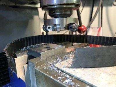
I was taking a 0.020" cut at a fairly slow feed and the chips and finish were looking good. I surmise that two bits hit the edge of the plate and the tapped hole simultaneously and it was enough to stop everything dead in its tracks.

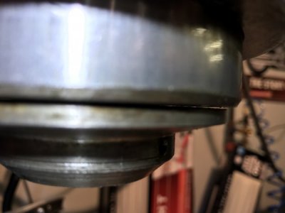
I noticed a gap between the spindle housing and spindle cap that was not there previously. I took out the allen screws and tried to take the cap off, but it seems to be held in place. I believe it has just peened itself on over the years, but I don't want to pry until someone with more experience than me can comment.
Qe6tEvOsQXC+EDQUfyxgzQ.jpg

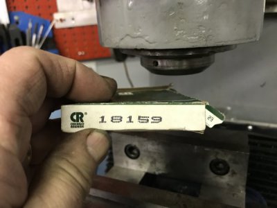
If I understand what I've read previously, this seal would go under the cap shown in the background? I bought it thinking my leak was coming from there, but...actually, I wonder if it's not leaking because there's no lubricant in there?
SaXmGDjERhqFz3BVSjJKDw.jpg

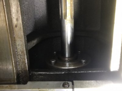
Although, it's obviously leaking from where the driveshaft goes into the head.
mv5Y3D%VS8Cgt7jvHlJSkg.jpg

I ordered belts for the main drive as well as the power feed. I already have shipping status and delivery date for tomorrow. I want to check and make sure nothing was bent or damaged when the belt snapped.

Comments and advice are invited for what to look for!
 
Last edited:
I can't edit my posts above, but I did discover that my spindle is drier than a bone and that's why it doesn't leak. I also realized the answer to my question about the spindle cap was answered by mktool in post #51.

Below is another little pearl I discovered in a thread on PM:

https://www.practicalmachinist.com/...wick-logan-milling-machine-165900/#post995039
"I have restored mine and have had everything apart except the drive shaft to head seal & bearing. very important the info that is out there does not mention the toilet seat oil fill port on top of the spindle that needs to be filled with #10 spindle oil."
 
@keflaman I had a bit of a back and forth on that further up the thread with @Brucepts who had sealed spindle bearings in his mill, whereas I have open, greased ones. I certainly intend to run my mill full of spindle oil at least until I manage to replace the spindle bearings with something newer and sealed.

I actually bought an NMTB 30 spindle that has the same number, if not necessarily depth, of splines, so I very well might switch to that in the future if I can find a reasonable set of NMTB 30 tooling, since I would much prefer the shorter change-out height. I did check its bearing journals vs the inner diameter of the quill, and I can buy similar bearings to what Bruce listed, just with different inner diameters, and get it to fit at least on that dimension.

Cheers,
Will
 
Nectropost time:


3D print to mount a tachometer to my MV100, looks great and fits *perfect*.

Cheers,
Will
 
Back
Top