My pulley housing was cracked at the lower plate and repaired by reinforcing metal bolted inside. I had thought about making a Rectangular box type housing out of 1” x 1/8” wall square tubing with a 1/4” base and top plate to accommodate my 1 hp 3 ph motor conversion. Looks like I can adapt the 3 ph Leeson motor to fit the original motor’s end plate. May have to lengthen the motor shaft though.

-
Welcome back Guest! Did you know you can mentor other members here at H-M? If not, please check out our Relaunch of Hobby Machinist Mentoring Program!
You are using an out of date browser. It may not display this or other websites correctly.
You should upgrade or use an alternative browser.
You should upgrade or use an alternative browser.
Rockwell Delta 21-100 Restomod (not restore)
- Thread starter JimBuchanan
- Start date
- Joined
- Sep 10, 2020
- Messages
- 34
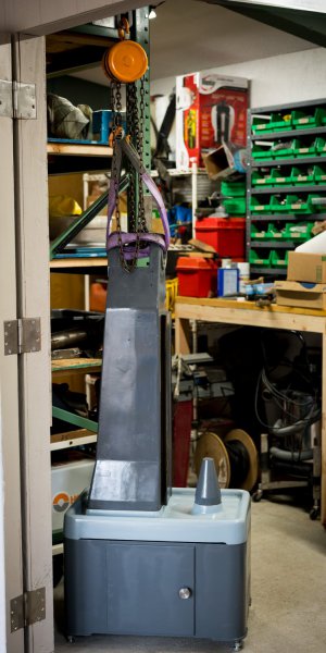
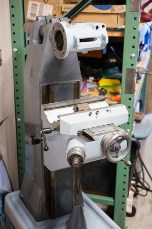
Slowly working my way up toward the head and motor. I have a wench-trolley on an I beam in my small shop to lift the column to position.
@OTmachine the pulley housing is aluminum, right? That could be welded. Having to make a housing, I'm leaning toward 2 parallel 3/16" steel plates separated by thick wall threaded rod and cap screws. I do have an original motor end plate with the hole and adjustment slot that I'm using and it helps with width dimensions. In my part of the country, lengthening a motor shaft is expensive, disassembling, welding and turning the shaft on a lathe. With a new head design and inverter motor, I'm only using the middle 3 pulleys and think I can use a stock 2 1/2" shaft length with no problem.
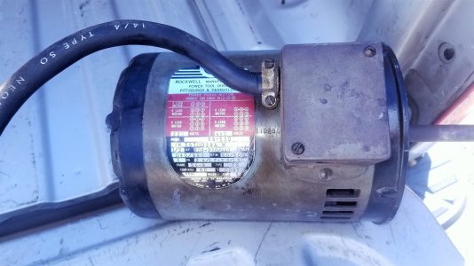
Speaking of motors, I have the original Rockwell motor I won't by using. Anyone interested for their authentic restoration? It's 3 phase, 1140rpm and 1/2 hp.
@OTmachine the pulley housing is aluminum, right? That could be welded. Having to make a housing, I'm leaning toward 2 parallel 3/16" steel plates separated by thick wall threaded rod and cap screws. I do have an original motor end plate with the hole and adjustment slot that I'm using and it helps with width dimensions. In my part of the country, lengthening a motor shaft is expensive, disassembling, welding and turning the shaft on a lathe. With a new head design and inverter motor, I'm only using the middle 3 pulleys and think I can use a stock 2 1/2" shaft length with no problem.
Speaking of motors, I have the original Rockwell motor I won't by using. Anyone interested for their authentic restoration? It's 3 phase, 1140rpm and 1/2 hp.
Attachments
@JimBuchanan,
Interesting watching your Resto-mod. I have had mine in my basement for a couple of years now. Good little machine. Yes, the housing probably could be welded, (will probably do this). I am retiring at the end of the year, so I can finally catch up on my round-tuits. The 1725 rpm 110V 1ph motor on the machine now gives spindle speeds of 370 to 6300 rpm, (Too Fast). The 3ph motor that I have has a 1” diameter shaft and about 2 1/2” long. Looks like I am going to make a shaft extension, so that I can just use the original step pulley, (looks to be 5/8” diameter bore). Fastest speed I can see ever needing is 3000 rpm for small carbide end mills. Going to add a return spring for the quill, (Hate the drop and kind of hard to use the fine feed). Adding a 50 graduation dial to the spindle stop rod. Had a LCD readout on it, which I took off, because it is actually easier to watch the stop. Easier to just use the knee for fine depth unless milling out a pocket on an angle. I have an old-school Enco trav-a-dial that I am adding to the X. Mine has an Asong power feed on the X, which started to go south, so I bought another feed for $115 on Amazon. Have to bore out another Handwheel to accept the gear for the new one. I have a 5” handwheel for that. Will fix the Asong so that I have a spare.
You will probably need to use some spacer tubes made out of something like 1” solid round stock in 6 or 8 places to add rigidity to your all thread and 3/16 thick plates.
Once again, I enjoy your post.
- Joined
- Sep 10, 2020
- Messages
- 34
The Y axis had handwheel resistance every 1/2 turn, so I put the screw on the lathe between centers and there was a bow of about .030" and it was visible when rotated. In a jig, I bent it more straight to an invisible .008" or =/- .004". Then, I shimmed the brass x-y double nut to locate the Y screw more in the center of the knee casting opening. Otherwise, the Y screw would sag down toward the bottom of the opening. The handwheel resistance was gone, and the action was very smooth. I was getting .018" backlash. Solutions to reduce that could be adjusting the shims to tighten up the Y nut on the screw; the only effect on the X axis would be null as the X nut would only be revolved a very small amount. Other option would be to try and find a double angular contact bearing that was adaptable to replace the existing 6202. And BTW, the knee and the X screw checked out on the lathe straightness test.
I can only imagine what happened to cause this. The 3rd handwheel was broken in all 3 spokes and the wheel itself was cracked open. I'm thinking the mill fell face first on that Y wheel bending the screw, and quite possibly bending the bronze X/Y nut to cause the Y screw to position more up or down. You never really know what you got when the mill comes in boxes of parts.
In this build the table would ordinarily be next, but I'm not quite sure how I'm going to clean it up. I'm starting on the head re-build at this point so I can tram the table and see if there is any front-back nod. If there is, I may scrape it flat. If not, I still have to deal with the abuse. A local Blanchard grinder priced himself right out of the market when he quoted his price. Then, there is the motor/pulley assembly waiting for me.
Attachments
I have never heard of the Rockwell Mill having a spring return on the quill??Make sure and let us know your method of quill return spring installation.
I know mine does not have that feature.
- Joined
- Sep 10, 2020
- Messages
- 34
To extend my train of thought above, maybe the plausible explanation of how the Y screw got bent and one of the 3 axis turnwheels broke by the mill crashing into the ground is the reason there is no pulley housing. It got broken too.
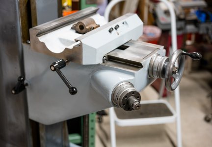
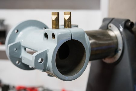
Anyway, the head has been prepped and mounted on the column for a convenient position to rebuild. Some of the Rockwell Delta literature indicate the head design has a way of compensating for quill head casting wear. Only after a couple of days of degreasing and paint removal did I notice the brass inserts next to the quill lock. The manual explains how these can be tightened to remove slack from excessive wear. This is the first piece to install.
I now have to make decisions about bearings. The easy part was ordering the MRC R16FF. The main reason I took a chance on this mill is an increase in precision over my gear head RF45 clone. So, it doesn't make sense to not get a duplex pair of angular contact bearings for the spindle, which I've found for a semi reasonable price.
The question I have is why the pulley pair has to be duplex high precision bearings? They are not directly connected to the spindle, but drive its rotation from contact with the 6 splines. I found a duplex set on eBay for about $110. Regular grade is about $50 a pair, so the real savings is only $60 or so.
Attachments
- Joined
- Sep 10, 2020
- Messages
- 34
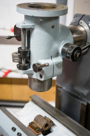
While I noted the quill adjustment screw to compensate for significant wear in the above , the pair of brass clutch wedges are part of the quill lock, not the quill wear adjustment.
I've decided to cold blue the steel pieces of the head to protect from rust. In the process, I noticed a few areas to potentially increase quill travel beyond the 2.5" stroke. For one thing, the double stop nut has a greater thickness than the remainder of quill travel at full down position. I've made my own version of the Morton depth stop for Bridgeports to fit the 7/16"-20 threads of the Rockwell. It is thinner and recovers that extra bit of travel the original 2 pieces take. The stop works the same as the Morton, pushing the button it slides quickly up or down. The 20 threads per inch gives .050" per revolution of the nut and 1/4 turn for .012" quick resolution for a positive stop. I will be looking closer at the quill casting to see if the vertical slot could be milled just a hair on the top and bottom for a possible 3 full inches of travel.
I will also consider making my own version of the #52 Depth indicator block in order to have a more square version for mounting surfaces for the read head of a quill DRO and still give access to the depth stop.
At this point its time to order some spindle bearings.
Attachments
Little Machine Shop has 50 graduation satin finished Dials that you can adapt for the quill feed stop. I had a DRO on my Quill stop but took it off because it is easier (for me) to adjust depth changes with a scale and the graduations on the dial.
- Joined
- Sep 10, 2020
- Messages
- 34
I've received the lower spindle NSK duplex bearings and installed them along with the R16FF upper bearing. The R8 bore is pitted from usage and age, but now clean and in light of the .01mm indicator hitting an occasional pit, I'm basically not getting any runout. This is encouraging. I also noticed there is no R8 locating pin in the collet. I'm now waiting on the pulley bearings.
I've been thinking about the pulley housing that I will have to make and the high aluminum stock prices here on the west coast. I was helped early on by a lead on some other head parts, so I'm reaching out one more time. Is there anyone in the community parting out a vertical mill head and has a pulley housing available?
I had to ask. In the meantime, with the spindle almost complete, I'm looking forward to mounting the table and tramming to see if there is any nod front to back.
- Joined
- Sep 10, 2020
- Messages
- 34
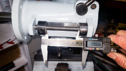
While I had the quill and spindle out, I finished fine tuning the quill travel and ended up with 2.9" travel. Most of that extra travel over the original 2.5" came from replacing the 2 disc stop with something shorter, here the quick release threaded stop. I was able to squeeze out a bit more on the lower end of quill travel.
The head is complete. The duplex bearings were mounted back to back and the inner and outer race markings were matched up to cancel out any radial imprecision. I used a NLGI 0 grade grease and loaded the bearings as demonstrated on a Youtube video. It was straight forward to tighten the duplex bearings together as when the races were cinched down the locknut would not tighten further, likewise on the bearing retainer.
I'm due to receive the 7007 duplex set so its time to work on the pulley housing design.