- Joined
- Apr 30, 2015
- Messages
- 11,278
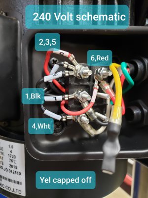
Sounds like you have somewhat of a handle on this so: very simply put, what we want is for the one reversing wire from motor #6 to connect to one side of the power line in forward and the other side in reverse. You'll need to sleuth it out, so put on your sleuth hat ")
Also, of course, power needs to arrive at motor wires 1 and 4 in both forward and reverse, sounds like one of those two cases is not happening
Many of these switches require some jumpers to work properly- I wonder if that might be?
Also, of course, power needs to arrive at motor wires 1 and 4 in both forward and reverse, sounds like one of those two cases is not happening
Many of these switches require some jumpers to work properly- I wonder if that might be?
Last edited: