Rons' Mastiff

ozzie46

Active User
Registered
Joined
Aug 5, 2011
Messages
217
Sorry I haven't been as active as I should have been for a while. Maye this will make up for it a little bit.

I started making this in the summer of last year. I made the crankcase from 4 pieces of aluminum.
I got the idea from a post by "nemt" on HMEM.
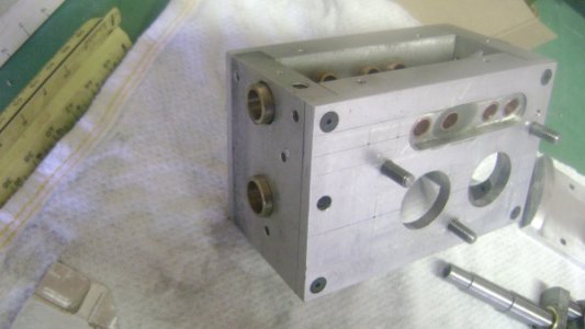
DSC03057.jpg

I used J-B weld to glue it together along with the screws.
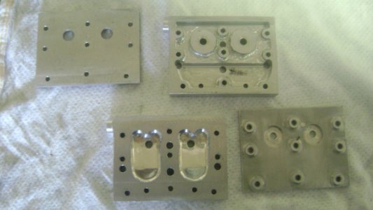
DSC03060.jpg


The heads are 2 piece to make the water passages as this is a water cooled engine. They will be glued together also. They still have to be profiled to the cyl contours yet.
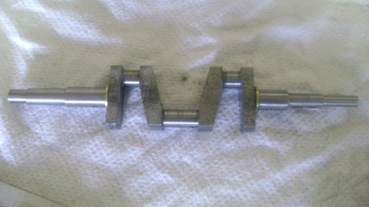
DSC03059.jpg

I was sweating bullets about making the crankshaft but it wasn't all that bad! I used some hot rolled steel and left it about .030 oversize and rested it for a few days before I finished it to size. I still have to thread both ends yet but it is true.
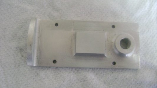
DSC03058.jpg

This is the top of the crankcase. The hole is to put the oil in and the raised pad is for mounting the carb or carbs as you can use 2 if you want.
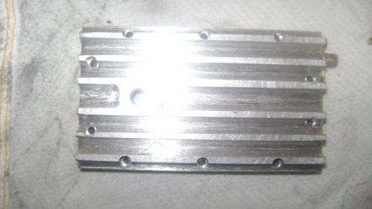
DSC03056.jpg

This is the bottom of the oil pan or sump if you will. Sorry about the bad pic.
DSC03055.jpg

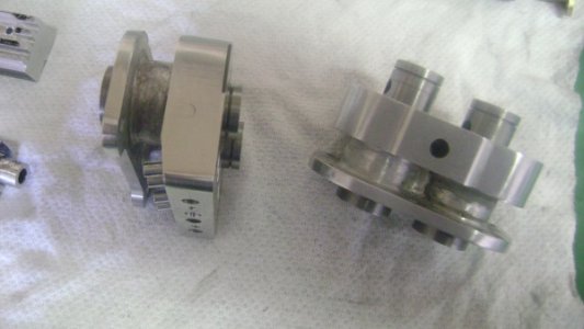
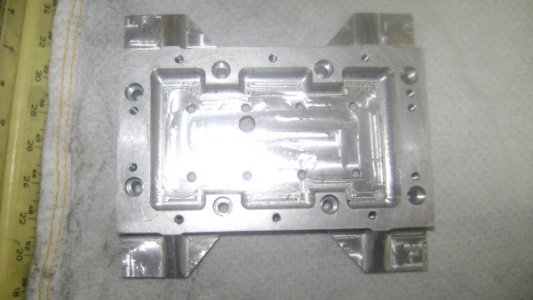
This part goes between the oil pan and the crankcase and has the engine mounting pads on it. How ever I goofed up and machined the mounting pads up side down. The will still work but it's not plan.

More to come.

Ron
 
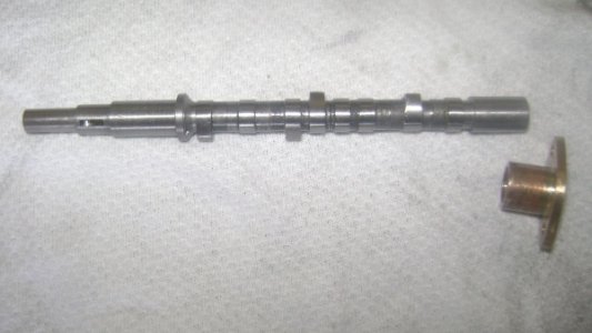
The camshaft was harder to make than I thought it would be. It is made from a central stainless steel 1/4 in shaft and the lobes are made and then glued on with locktite . I will post more on this later when I take pics of the tooling to make it.

DSC03054.jpg

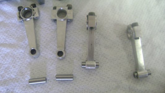
The rods and the wrist pins. As the wrist pins are floating they are drilled 3/32 for aluminum or some other kind of pin with a head that won't score the cyls.

DSC03053.jpg


The cyls have wet sleeves and were lapped using the tool that Len Mason described in his article on building the Mastiff. Ramon has shown the tool in his thread on lapping. The pistons were lapped to fit the cyls also. I made the rings and heat treated them too.
That was an interesting project in itself.

DSC03052.jpg


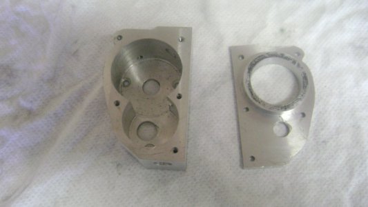
This is the timing gear housing for the front of the engine.

DSC03063.jpg

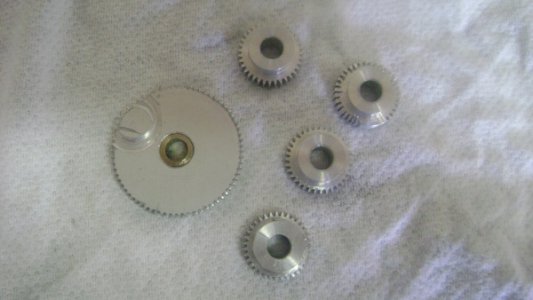
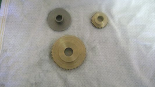
Here's the gears. I would like to take the opportunity to thank everyone who offered advice on gear cutting when for it a while back. It came in very handy and after I just got brave enough to do it I was surprised by how relatively easy it was. I cut them on a rotary table after practicing an some aluminum blanks first.

These are the practice ones.
DSC03062.jpg

The real ones.

DSC03061.jpg


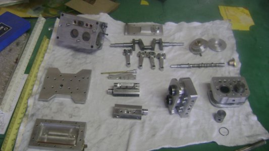
And a family portrait so far.

DSC03051.jpg

Ron
 
Beeeautiful. It was getting lonely here, Thanks for posting your build.

"Billy G"
 
Thanks Bill, will try to keep it nearly as good as yours.:)):))

Ron
 
You're kidding right? I don't see you having any problem in that area Ron.

"Billy G"
 
Great work so far on your engine. If I might make a suggestion. In your posting you mentioned about using aluminum buttons in the ends of the wrist pins to prevent the pins from scuffing the cylinder walls. Rather than use metal, any metal, why not get a piece of Teflon or Delrin and make them from that. I can't say that the metal wouldn't scuff the cylinder walls but after all the work I just wouldn't want to take the chance.
gbritnell
 
Thanks George for your comments. I think I might have some teflon around. Mr. Mason had mentioned using light alloy and I figured that meant aluminum so that was my thinking.

Ron
 
Some more of the Mastiff.

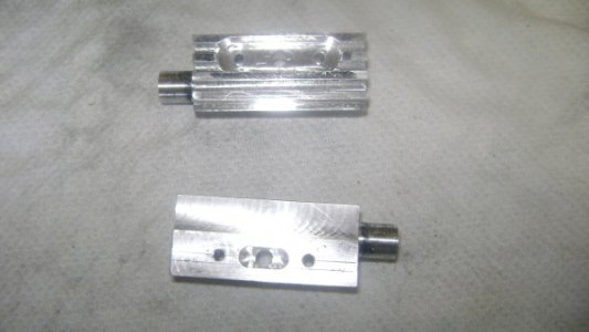
These are the combined intake/exhaust manifolds. I still have to drill the exhaust port holes yet.

DSC03066.jpg

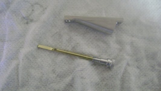
The oil dipstick and housing.It will be bolted to the side of the crankcase.

DSC03067.jpg

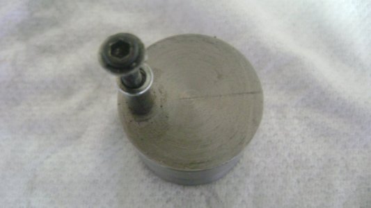
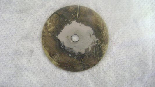
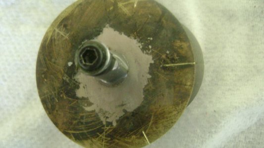
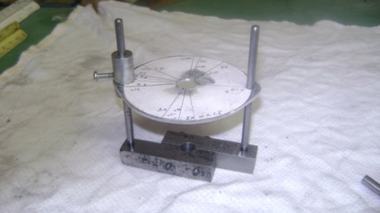
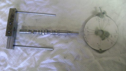
The fixture for offset turning the cam lobes and the plate the loe blanks are soft soldered to for turning.

DSC03070.jpg

DSC03069.jpg

A posed shot of the complete setup for turning.

DSC03071.jpg

The fixture will hold material for 2 lobes to be turned at a time.
One side of the plate is for intake and the other side is used for exhaust.

After the lobes are turned they cut in two with a thin slitting saw and finished machined and hardened as they are made out of drill rod/silver steel.

Now the fixture for assembling the cam lobes onto the 1/4in stainless steel rod to make up the cam.

DSC03074.jpg

DSC03073.jpg

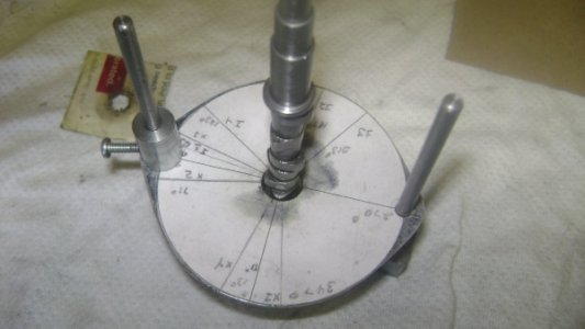
A posed shot of the setup.

The cam lobes are lined up with the appropriate marks and lock tited on.

DSC03072.jpg


That's it for now, hope you enjoy it.

Ron
 
Ozzie, where are ya. Ya can't leave us hangin like this. :lmao:

"Billy G"
 
Yup, small Teflon buttons on each end of the wrist pins and you will be golden. Circlips and grooves are a major PITA and have a tendency to loosen and fall out when the engine is running under a load. Didn't see an oil pump either. Are you planning to use splash lube or is the pump still forth coming? It would be neat to build a belt powered pump like they use on NASCAR engines with dry sumps. Do you have a plan for displaying it such as running an overhead power shaft or a small generator made from an alternator or something like that? Just a thought.

Bob
 
Back
Top