M
Mystery2
Forum Guest
Register Today
Hi folks
I need to build a rotary phase converter to power a three phase welder .
I think I have a decent understanding of how to do a basic build but I do have some questions.
I already have a 5hp converter with a phase Kraft panel powering my shop so I'd like to keep this one very simple ( and cheap ) .
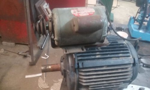
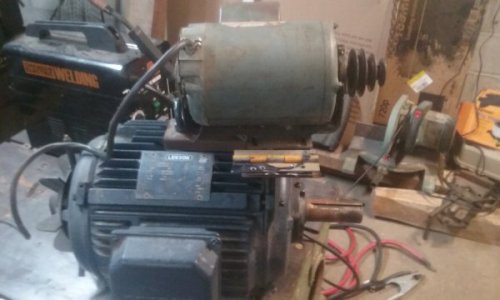
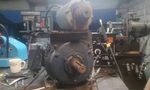
So , I have a 15hp leeson 1750 rpm motor I am going to use for the idler and a 1hp single phase 1750 to use for a pony motor to start it .
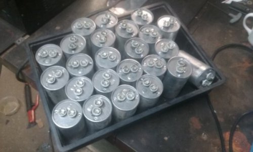
I have a bunch of 46uf 530v caps and a 60 amp knife switch .
Being as for right now this is going to be single purpose ( welder ) and not daily use I don't plan on using any contractors or anything fancy , just simply get the idler spun up to speed with the pony and use the knife switch to power the idler .
Now here's my questions .
First is wire sizes and such .
What size wire should I use from my breaker panel to the motor .
Total run lengh is less then 8 feet . Is 10 gauge enough for that short a run ?
And do I need to use the same size wire for wiring in the capaciters?
And terminal blocks , with a separate block for each leg do I need to use blocks rated the same as my breaker or can I use say a 15 or 20 amp block for each leg .
Balancing capacitance .
Using L1 and L3 as my powered legs and L2 as my generated leg
If I add say 3 of my 46uf caps from L1 to L2 do I need to run a like amount of capacitance from L3 to L2 to properly balance things or would a single 46uf cap be enough . Or should I maybe run two caps from each powered leg .
I have no idea how sensitive a older transformer welder is to voltage
And unfortunately I don't have a clamp on meter to checks things properly so I'm just kinda winging it .
Thanks in advance for the help .


