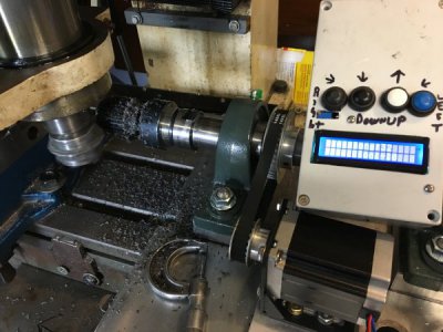
Rotary Table Conversion

Hi Chris,

Looks like you've made a nice addition to your lathe and rotary table setup! I am glad you've found the project to be of use. If you have any suggestions to change of add features to the software, please let me know.

Would you mind if I linked to this thread from the DM forum? Just like to see various implementations listed there.

Anyway, nice job and good luck with all your projects.

Gary
 
Last edited:
No problem Gary. Link away. I enjoyed looking over your aircraft build as well BIG project. Hope you are enjoying your Thanksgiving.
C
 
oh great, the 614 page to do list wasn't long enough, I needed one more thing to add......:cpa:

Seriously though, thank you Gary for the great info and thank you Chris for bringing it to my attention.
 
I been checking this idea out for a bit, now the big question... Is there a feaseable way to make something like this but without the stepper motor turning the work. You just turn the work by hand and the display tells you where you at on degrees. Im thinking something like a crank angle wheel from a car or something like that. This would be for indexing on a lathe
 
Is there a feaseable way to make something like this but without the stepper motor turning the work.

Sure there is. If you look into "push-to" telescopes, they work by letting you input the star you want to look at, and then tell you which direction to move - "push" - each axis on the telescope until it points at the star. Of course, the telescope has to be aligned properly first. (Search for "DIY push to telescope")

The way those work is using an optical encoder on the shaft of each axis which allows the computer to sense rotary movement. So, you mount a shaft encoder (the good news here is that they used to be very expensive, but have gottten cheap, like this one, or better yet, this one) on the on the cranked shaft, move the crank to some reference position, press a button, and then move the crank until it says you are on the "nth" position you wanted. Lock it down, make the cut, and repeat until done. By placing the encoder on the shaft of the crank, instead of the work piece, you increase the resolution of the encoder by whatever mechanical advantage to have in your gearing - i.e, if you have a 40:1 gear ratio like on a rotary table, your encoder just increased its resolution by 40.
 
Last edited:
Hi fellas. Sorry to wake up an old thread. Building GaryLiming indexer. Cannot get help from Gary yet? Not having any success on showkeys for ‘right’ zero does not show. Then when running stepper2.3 left button is the same as down and select does not work at all. I think the values in lcd keys need matching to my shield as they are indeed different than Gary used. Still no explaining why 0 is not zero on every shield?
TIA anyone?
 
Fellas, got it all sorted out. Adjusted the lcd keys integer values to suit my shield (dfRobot) and it is functioning flawlessly!
Very pleased with Gary's sketch. Looking forward to using this on the mill. Need an enclosure first.
Thank you Gary!!
 
288353
I also used Gary Liming"s Arduino code Indexer along with a YouTube Video from MyFordBoy

It works flawlessly. I love it.
 
Last edited:
Back
Top