Rotary valve steam engine build

joeschuit

Registered
Registered
Joined
Sep 20, 2013
Messages
3
engine_zpsb3fa9004.jpg

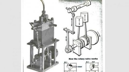
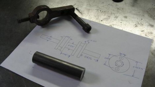
This is my first steam engine, so I went with one that didn't involve casting parts or machining gears. This one is published in the December 1961 issue of Popular Science. It has about 30 parts, all starting from easy to get steel, aluminum, and brass/bronze stock. I decided to start with the hardest part, the crankshaft. I took the original dimensions(in fractions) and made up a cad drawing to print out. This piece needed a 1"x4" steel rod.
DSC02461_zps1802414e.jpg

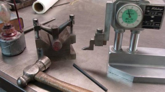
After facing off the ends, I used a locking v-block to scribe in the center and outer lobes.
DSC02462_zps1bc39d5f.jpg

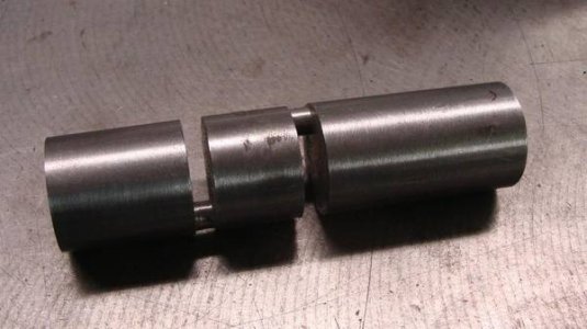
I've only used a cutoff tool in the lath a few times. The distance between the lobes are only 3/16" so there isn't many choices. I went at it slow and steady, cutting each one a bit at a time.
DSC02463_zps7f13c40e.jpg

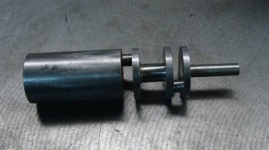
Once those were cut, it was much easier to remove the rest of the material.
DSC02464_zps1a8c2c00.jpg

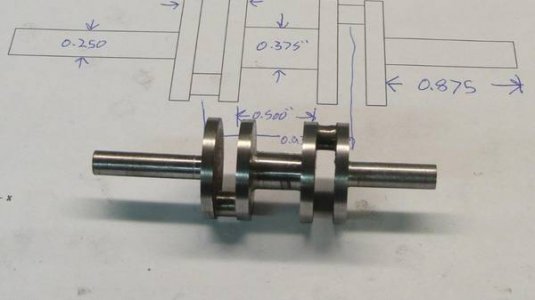
Here is the finished product, before final sand and polishing:
DSC02465_zps08447cdf.jpg

I had about 5 hours of lathe work on this piece. I had some time today to get another piece of the puzzle done, the base made out of 1/4" aluminum.
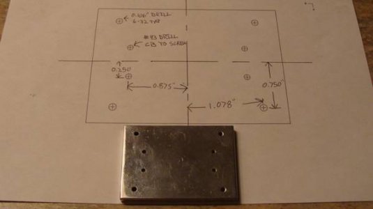
DSC02466_zpsda4c3dc9.jpg

I'm hoping to get a few parts done here and there and updating often. I'm always open to questions, opinions, or if there was an easier way of doing things. I'll try to get a few pics of the machines I'm using as well. As being my 2nd post, I'm not sure if off site photo hosting is frowned upon or not. It's a bit easier for me to keep things organized. Thanks, Joe
 
Very nice, I will be following your build.
 
Nice work on the crankshaft. Will be watching your progress. Thanks for posting your build with pictures. Roger
 
So I figure you used an off-center set up in a 4-jaw to turn the crank pins - right?
How did you locate the second crank pin to be 180 deg from the first?

Great project.
Terry S.
 
I went with what the instructions provided to machine the crankshaft. It said to scribe center lines at 90 degrees, punch/center-drill the center, along with scribing lines 5/16 from center, and punch/center-drill. When I scribed the second center line, I used the height gauge to go 5/16 up and down to mark the offset centers. I then chucked up the crank on the offset centers using dead and live centers and used a dog for "grip". I do have a 4 jaw chuck, but I have very limited experience with it.
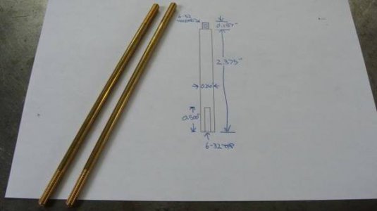
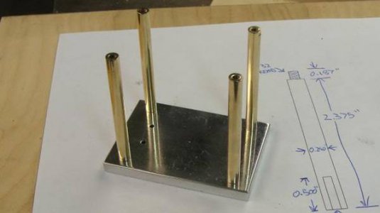
I made a mcmaster order today that will net me the rest of the material I need, along with some 1-72 taps. I had some extra brass scrap to be used for the base support columns.

DSC02469_zps48bf70b7.jpg


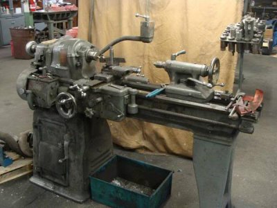
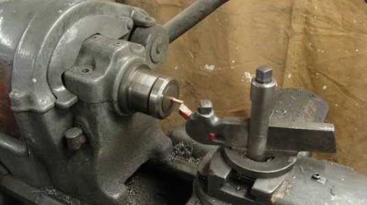
Here's the lathe. An older southbend 13".

DSC02471_zpsca3b3f20.jpg

DSC02470_zps246b1c92.jpg

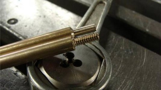
The ends are threaded to 6-32:

DSC02473_zps193e47cd.jpg

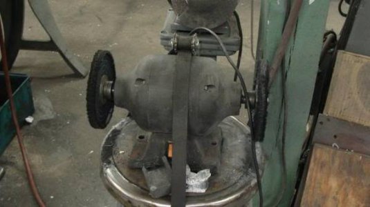
My diy 1/3hp buffer:

DSC02474_zpse3170c37.jpg

The final product:

DSC02476_zps6aabb836.jpg
 
Back
Top