- Joined
- Jan 21, 2021
- Messages
- 452
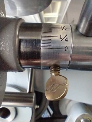
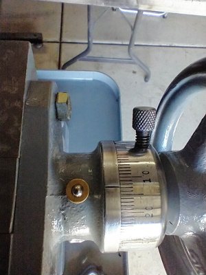
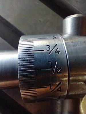
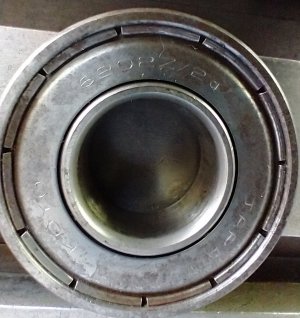
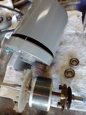
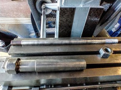
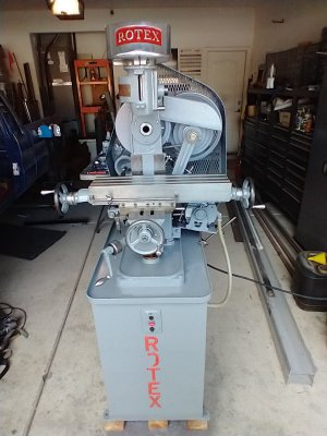
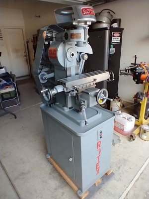
The gals at work that have to do this, they use a small bottle nose container, put the paint as best you can, then swipe away the rest that is too much, with small, like a matchbook card board , squares, then wipe with a rag of acetone after a few minutes:<)I think I have everything cleaned and painted. I can't really finish until I get the new bearing.
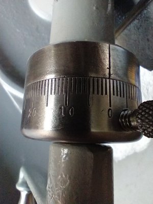
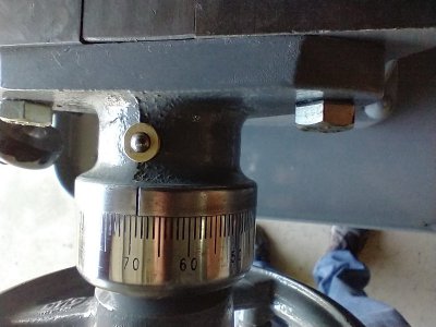
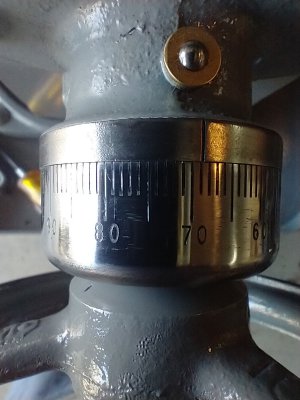
I think it will help my old eyes see the dials if I paint the lines and numbers. Anybody have a good method to do so?
Good luck!

")