Royal Blue #3

I didn't get a lot done today as I was having problems with my X axis power feed. I did get it going for now but it won't last long.

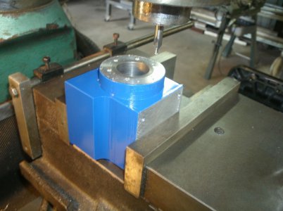
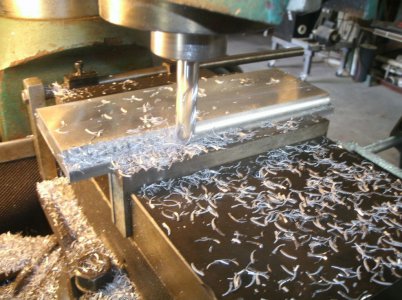
Engine base plate is the next item to be made so I can tie everything together and make sure things will fit. I thought 1/2" aluminum plate would be about right but I didn't have any pieces large enough. I do have some 1/4" plate but I don't think that would be rigid enough and counter sinking screws up into the bottom would not leave much material for holding. I do have some aluminum plate that measures 0.669 but it is not square or true to any surface. I did cut it close to the width I wanted and then over to the mill to true it up.
GEDC4535s.jpg

Here it is almost ready for some holes with some fancy side cuts.
That's all for today

Thanks for looking
Ray
 
Ray,-

Liked the way you machined the crank. Milling away material is a great time saver and less risky. Will follow your post.
 
Thanks to all
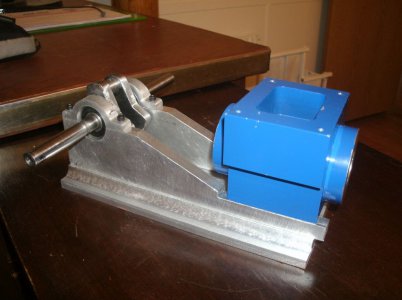
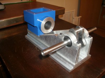
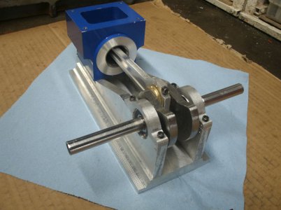
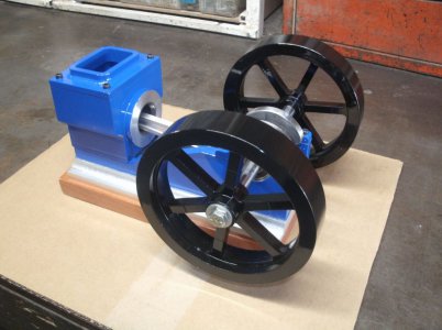
I got everything bolted together and aligned up today.

GEDC4538s.jpg

GEDC4540s.jpg

I had better make the connecting rod next to see if my scribble of a drawing is correct or if I will have to move the cylinder further away from the crankshaft.

Thanks for looking

Ray
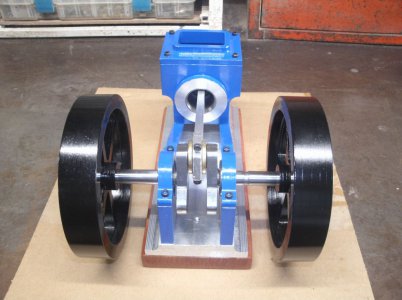
 
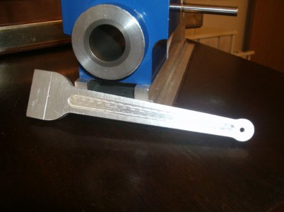
I had to mow the yard (2 1/2 acres) this morning so I didn't get much shop time today but I did get the connecting rod roughed out. It looks like it will work but it will be close. The cylinder ended up about 0.250 closer to the crankshaft then I originally wanted it because of a brain $art on my part. So we will see after the rod is done if there is any interference.

GEDC4547s.jpg

I am going to get my eyes checked tomorrow afternoon hopefully to eliminate some of my goofs.

Thanks for looking
Ray
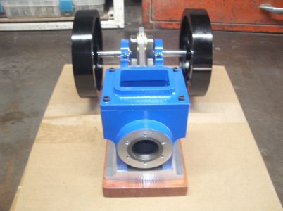
 
OK eye exam done and new glasses on the way and no problems with my eyes the Dr says.

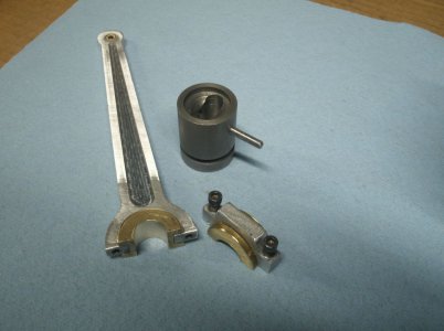
I don't know how other people make their split brass bushings but this is the way I made mine.
I know the crank throw is 0.500 and I should have the inner part of the bushing about 0.125 thick so some 1" round brass should work fine.
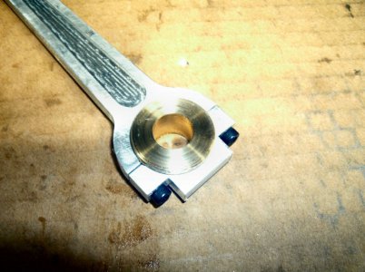
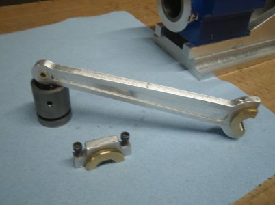
First I put the roughed in connecting rod in the mill vise pointing up on the crank end. I then milled off a section on each side of the rod for the rod bolts to sit on. Next I drilled the rod cap bolt holes all the way through the rod at the recommend size for 6-32 screws. I then cut off the rod cap using a hand saw with a 0.010 blade. The rod cap holes are enlarged for the bolts to pass through and the rod holes are tapped 6-32. Then I bolted the cap back on and drill the rod end out to 31/64 that will be the OD of the inner part of the bushing.
On the lathe turn the bushing center part down for a nice fit to the rod and rod cap. I now drilled the center of the bushing to just under 0.500 and parted off the sides to the width of the crank throw and parted off the bushing.
GEDC4549s.jpg
As shown in the picture the cap doesn't quite tighten down to the rod and that is because that when I cut the bushing in half it will be smaller and the center hole is no longer round. Carefully mark the cut line of the bushing with the saw and cut the bushing in half in the vice. Reassembled the rod cap and notice it now fits very nice. I then re-drilled the center hole to just under 0.500 to make it round again and finished with an adjustable reamer to slowly get a nice fit on the crank journal.

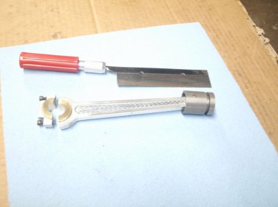
This is the completed rod with a brass bushing for the piston end.
GEDC4551s.jpg
GEDC4554s.jpg

And the saw I used.
GEDC4556s.jpg

And all assembled and working smoothly.

GEDC4557s.jpg

I was shooting for a compression ratio of about 6 to 1 and I ended up at about 5.8 to 1 after final assembly. Close enough for me.

You may notice from the picture that the crank end of the cylinder got shorter. Well I did have an interference problem with the connecting rod and the cylinder end so I shaved off about 0.150 in the lathe to get enough clearance for the rod.

I think I will start on the flywheels next.

Thanks for looking
Ray
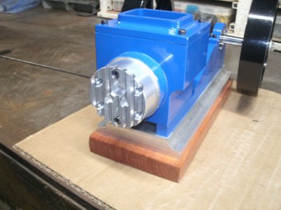
 
I was able to make some progress on the engine the last couple of days.

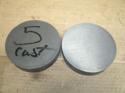
I got these from Federal Express.
GEDC4561s.jpg
+5" round X +1" cast iron cuts.

GEDC4566s.jpg

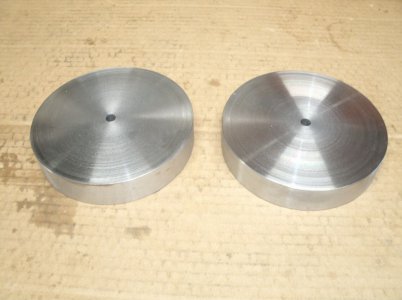
All trued up for the next operation.

GEDC4568s.jpg

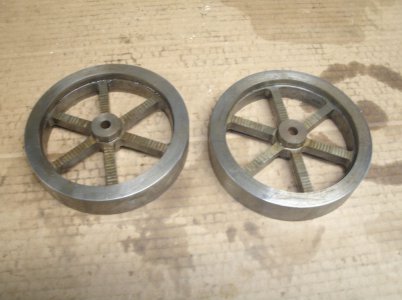
Got them roughed out today but still a lot of cleanup left to do and cut a taper on the inside for the crankshaft. I think I will try a 7 degree angle so that the taper will be longer and since the flywheels are 1" I will have enough width. I will have to try one and see how it goes.

Thanks for looking
Ray
 
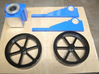
Well the 7 degree taper worked just fine so I cut both flywheels and tapered the crankshaft on both ends. I cleaned up the flywheels and did some more painting.

GEDC4571s.jpg

Drilled and taped the cylinder for the head bolts even though I haven't decided exactly how the head will be made.

GEDC4572s.jpg

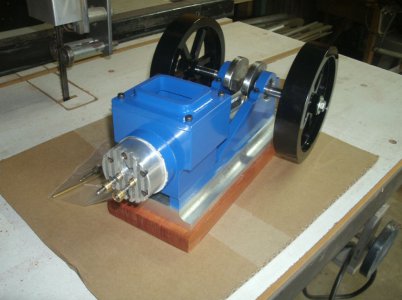
I added a cedar wood riser so the flywheels would clear and did an assembly check.

GEDC4575s.jpg

The stance is quite wide but I wanted enough room to easily add all the stuff that goes on the crankshaft. On my other engines I always seemed to run out of room on the timing gear side. I can recut the tapers on the crank later if I want to narrow it up but I will leave it like it is for now.
GEDC4577s.jpg

Front view and the six head bolt holes.
Maybe the cylinder head is next item I should work on.
GEDC4581s.jpg

Thanks for looking
Ray
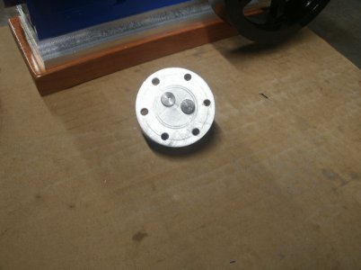
 
I decided on a rough sketch for the cylinder head with some cooling fins. I don't know just how much heat they will dissipate but they look nice.
I drilled the head bolts in the head and mounted it to see how it looked. I must have done something right as all the holes lined up.

GEDC4583s.jpg

The valves are moved down 0.100 from the center line of the head to give more room for the spark plug plug recess above them.
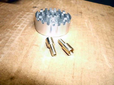
The valves will be 0.3125 in diameter with 0.125 diameter stems. I had thought about 3/8" valves but after my experience with two other engine builds I decided it wasn't necessary.
The valve guides are made of brass with a 45 degree angle for the valves and are pressed in to the head.
GEDC4585s.jpg

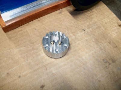
Here they are with the valves in place.
GEDC4589s.jpg
GEDC4591s.jpg

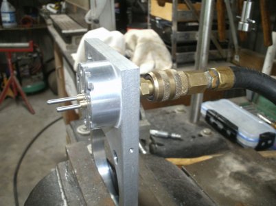
Next is the valve grinding and lapping and to do that I use a pressure fixture. It is made from a piece of scrap aluminum with a shop air fitting on the back.
This provides a reliable test stand to check your progress but more importantly to find just where more work is needed. The valves will seat better as the engine is run but you have to get it running first.

GEDC4595s.jpg

Thanks for looking
Ray
 
I spent around 8 hours yesterday and today working on the valves. I made the valve spring keepers and even made some valve springs. The intake spring is made from 0.010 piano wire with a wide spacing and the exhaust spring is made from 0.014 piano wire with a close spacing.
Most of the time was taken up on lapping the valves. I wanted to do an especially good job of this as if you remember from earlier the piston doesn't have a ring on it. I found that I do have a respectable amount of compression so the piston stays ring less for now.

GEDC4603s.jpg

Thanks for looking
Ray
 
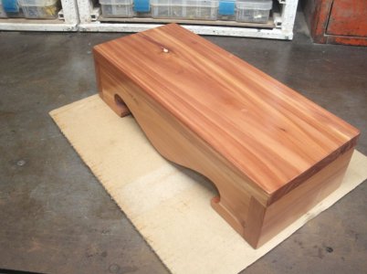
I used some cedar that I had to make a stand with a wider base for the engine and to have some place for the electronics and battery inside.
I have been working on this for several days off and on and finished it up today.
GEDC4598s.jpg

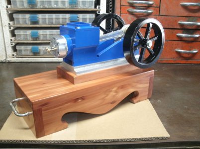
And here it is with the engine mounted.
What do you think?

GEDC4606s.jpg
On another engine I had built I found that there is no good place to pick up the engine with out possibly damaging something so I added handles to the end of the box. I also made the box long enough for a gas tank and an On/Off switch.
I am open to suggestions for the gas tank design as the other engines I made I just used copper pipe.

Thanks for looking
Ray
 
Back
Top