Running a mill or lathe on a generator

Diesel is best, the fuel does not go bad like gasoline does but is expensive. If you get an inverter type generator, make sure it is sine wave and not modified sine wave. in case you will be running electronics like a computer or CNC conversion.

Diesel is lower cost than gasoline. It's the physical plant that costs more. There are many other reasons for running a diesel plant. Just be sure to find an engine of known brand to your parts people.

There are ways to "adjust" the synthetic sine wave of an "inverter". Some electronics are sensitive, some are not. I have used an inverter short term with my splicing(fiber) machine with no ill effects because it used a "switching" supply. A motor load will not have any problem. A VFD possibly would. I personally do not like a synthetic sine wave plant. More personal taste than any real problem.

The simplest way to "adjust" a synthetic sine wave is to have a magnetic device across the line full time. Such as a transformer. However, the cost of a transformer of sufficient size is such that if the cost were added to that of an inverter, you could just buy a true sine wave machine from the "git go". Keep in mind that I am "old school". I won't go into "magnetic amplifiers" and "sensodynes", but that is how far back my knowledge base goes.

Your last post implies that you are good at "scrounging". If that is indeed the case, a transformer would alleviate any concerns about "quasi-sine wave" generators at little cost. The bottom line is that you would have no concerns about running a motor on most any supply. They are usually rated for 50-60 cycles anyway. It's the electronics that are of concern. If there are none, just run whatever plant you have.

.
 
Wow, that is quite an assortment of generators you have.

You did not mention what size generator is on the Deutz F1L812 engine. If it is big enough I would look further into that, it is old, parts may be an issue.
Whether the filter is too restrictive or not, air in the line is a leak, you need to find it.

I did find a thread on that engine that may help you.

I do have a low time 3500 W commercial Baldor gen that I would like to sell and get a smaller one that is either diesel or propane powered.

I think the diesel is10 horsepower and the generator puts out 25 amperes at 220 volts running at 1800 rpm.
Parts were ordered for the Honda EM6500SX so will see where that goes....
 
Diesel is lower cost than gasoline. It's the physical plant that costs more. There are many other reasons for running a diesel plant. Just be sure to find an engine of known brand to your parts people.

There are ways to "adjust" the synthetic sine wave of an "inverter". Some electronics are sensitive, some are not. I have used an inverter short term with my splicing(fiber) machine with no ill effects because it used a "switching" supply. A motor load will not have any problem. A VFD possibly would. I personally do not like a synthetic sine wave plant. More personal taste than any real problem.

The simplest way to "adjust" a synthetic sine wave is to have a magnetic device across the line full time. Such as a transformer. However, the cost of a transformer of sufficient size is such that if the cost were added to that of an inverter, you could just buy a true sine wave machine from the "git go". Keep in mind that I am "old school". I won't go into "magnetic amplifiers" and "sensodynes", but that is how far back my knowledge base goes.

Your last post implies that you are good at "scrounging". If that is indeed the case, a transformer would alleviate any concerns about "quasi-sine wave" generators at little cost. The bottom line is that you would have no concerns about running a motor on most any supply. They are usually rated for 50-60 cycles anyway. It's the electronics that are of concern. If there are none, just run whatever plant you have.

.

Are you saying I could clean up my AC by connecting up a 220 volt transformer in parallel with the line
without connecting the secondary? That sounds interesting to me.
 
Hooking a transformer across the line unloaded (open secondary) will correct a square wave to some small extent. To get better results, the transformer should be between the generator and the load. Based on your previous posts, a 5KVA 240/240 transformer would be large enough to carry the normal(<65%) load. I offer an article(small book) I wrote several years ago as reference;
The part you would be referred to is deep(ppg 20+) into the text. It does not give specific formulas, rather an insight to the hysterysis of a magnetic circuit. There would be a major effect on power factor, down perhaps to 65% lagging. But you're talking field use so it really doesn't matter that much. The average power plant is little better, 85 to 90%. The only thing you would need to watch is when your output goes near the max.

.
 
Last edited:
Bi11,

Would hooking an appropriately sized inductor across the line do the same thing?
 
An inductor connected "shunt" will give the same result as a transformer connected "open". Very little effective results. . . An open transformer is essentially a shunt inductor. The bottom line here is that the more load current carried by the inductor, the transformer, the smoother the output will be. What is wanted is the magnetic hysteresis effect of current in the inductor. So the more current drawn by the inductor, the more magnetic "offset" is visible. This is limited, of course, by the maximum current of the inductor.

The most direct result will be seen when the inductor is connected in series with the load. This, however, requires the inductor to carry the full load current. If such an inductor is available, by all means it can be used.

A simpler solution is to use a transformer to carry as much of the load as possible. Again, limited by the transformer KVA rating. In the case of a portable generator, 5 KVA minimum. Most "non-technical" people will see the transformer as a straightforward transformer. Connect one side to the generator, the other side to the load. A series inductor, while fully functional, can be easily mis-interpreted as to its' connections. KVA is the normal rating for inductors or a transformer. It means thousands of "Volt-Amps". Simple arithmetic will give the actual numbers. Volts times Amps times 1000.

Many "industrial" transformers will be 240/480 volts on one side and 120/240 on the other. Connected 240 on both sides allows the "secondary" to be split for 120 volts to be pulled off. The effective neutral, the center tap, should be referenced to ground, if possible. The connections will be labeled on the "high" side as H1, H2, H3, and H4 with the "low" side as X1, X2, X3, and X4. Connected with H1 and H3 as one line, and H2 and H4 as the other, allows 240 volt input. For the secondary, X1 is one side, X4 is the other. X2 and X3 are connected together as a "neutral" and grounded if possible. This allows for 240 volts from X1 and X4 with 120 volts from X1 to X2 or X3 to X4. The 120 volt lines should be balanced as much as practical.

There are many other possible connections for such a transformer. But there are two hard and fast rules that must be kept in mind. The voltage and current applied must never exceed the name plate rating. i.e. When H1 and H2 of the above transformer are connected to 24 volts, the output on X1 and X2 will be 12 volts. But the KVA is still rated at 240 volts and current must be kept at that level. The other is that all voltages given are AC at 60 CPS. DC can almost never be applied.

That last paragraph is digressing wildly, I am going into lecture mode. It really is not relevant to your case, just a comment.

.
 
Maybe using a 1 to 1 transformer may be the best clean up action.
 
Essentially what I spoke of above. Just be sure to use proper voltage rating. Getting both 240 and 120 would require some sort of center tap.

.
 
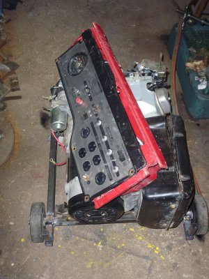
I'm pretty sure of my chances of getting the Honda EM6500SX running as it has great compression.
I decided to make a frame for it and mount it on wheels as just the generator and
motor weigh about 200 pounds. It was a bit difficult lifting the unit and configuring a wheeled base but
in the end it is on the base now and I can proceed with building the top part of the rack that holds the
fuel tank and electrical stuff. I used a skid steer to lift it using some ropes to hold on to it so I didn't
break off any aluminum brackets. I am making the top part of the rack removable as it would be no
easy task to set the generator unit into a one piece frame. It will have handles, possibly foldable,
to wheel it around.

P1020845.JPG
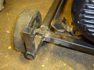
The wheels are solid rubber about six inches in diameter, good enough to move on a relatively flat surface. P1020846.JPG
The vertical tabs will allow me to build the top part of the rack with the generator unit sitting on the wheeled base.

The generator was a basket case found at the local scrap yard so just a fun challenge to get it together and hopefully
operating.
 
Back
Top