Saving a Logan 825

bhusted

Registered
Registered
Joined
Jun 15, 2019
Messages
119
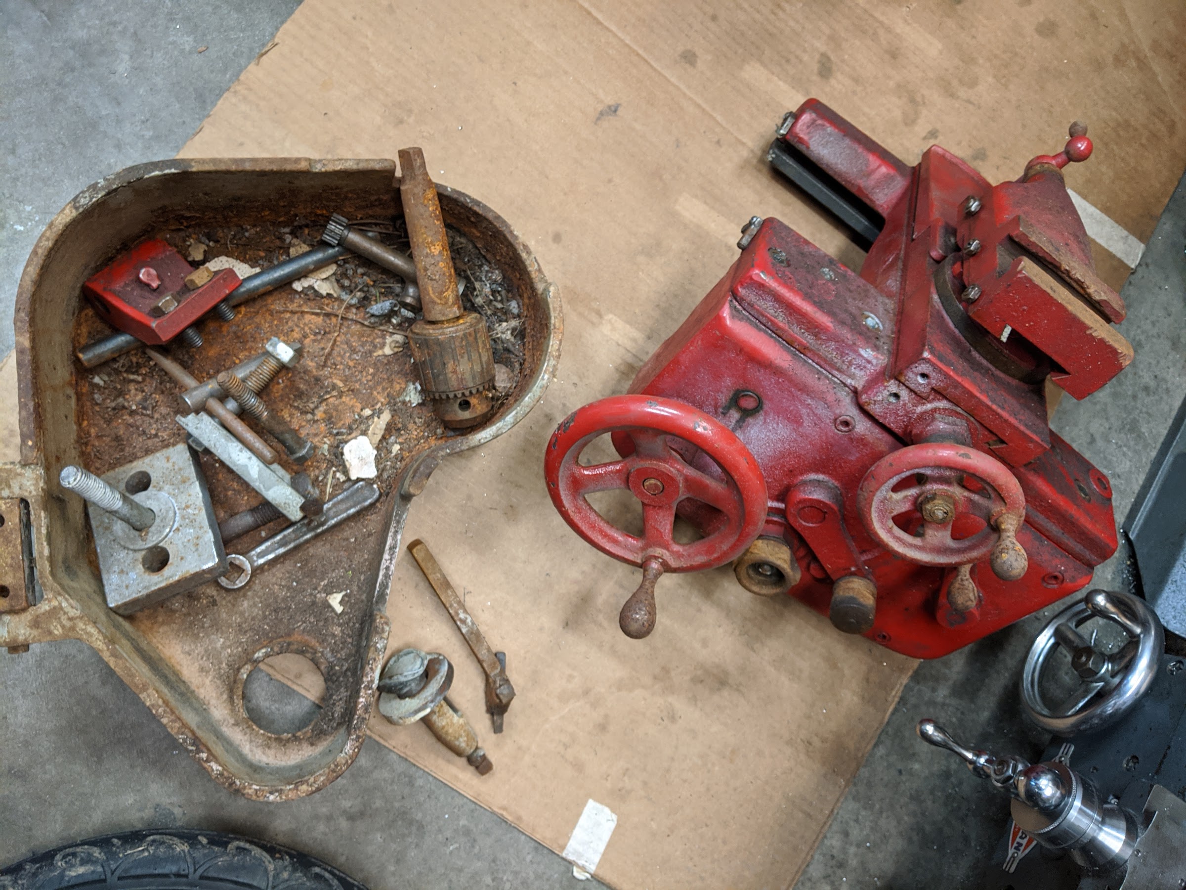
I managed to pick up a Logan 825 on CL for less than scrap value. It had been disassembled by some previous owner many years ago and the guy I bought it from was just trying to clean the place out and didn't want it thrown away. For the sum of $25 I came home with ~300lbs of cast iron. As far as I can tell, most of the parts are there (Bed, head-stock, tail-stock, carriage, QCGB, etc.). Some parts are rusty, others are slathered in paint, and some have been spray painted red??? It really is a basket case, but I'm going to work through and see if I can get it back together and give it a little TLC.

One of the issues I've encountered right away is that it was made to be mounted on Logan's stand with the motor mounted underneath. Since I don't have the stand and locating one would be a significant challenge, I'm trying to get creative. I have a spare 3/4hp Baldor motor that would suit it, but without the intermediate jack-shaft, it would only be one speed and much too fast. I've seen some people using permanent magnet DC motors on lathes so that they have speed control. Would one of these have sufficient power to run the lathe with a smallish single reduction? Obviously I'd need something bigger than the treadmill motor others use on the 7" mini-lathe.

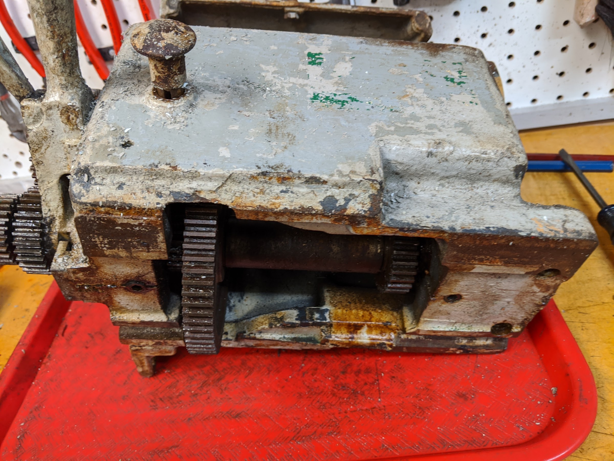
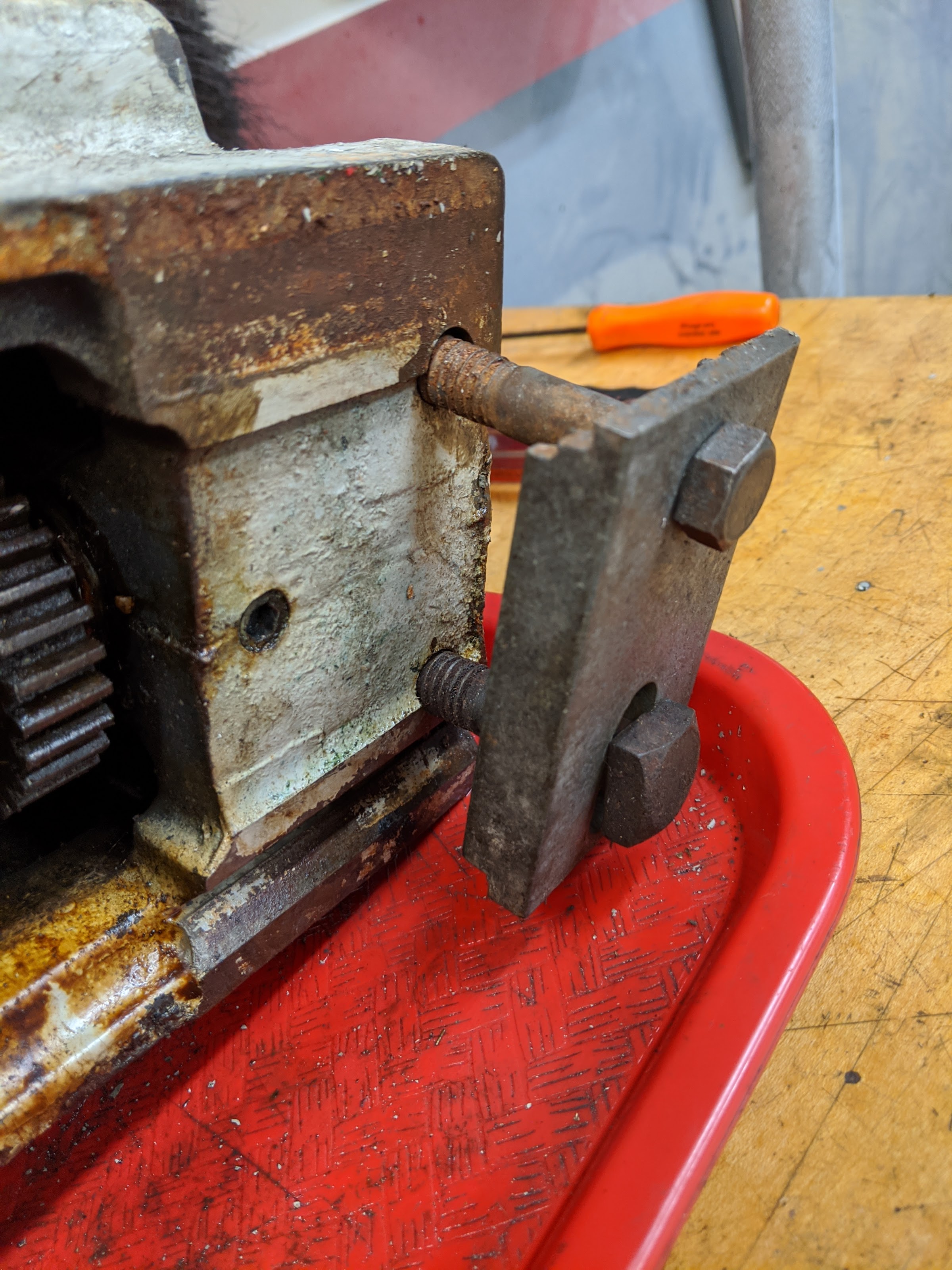
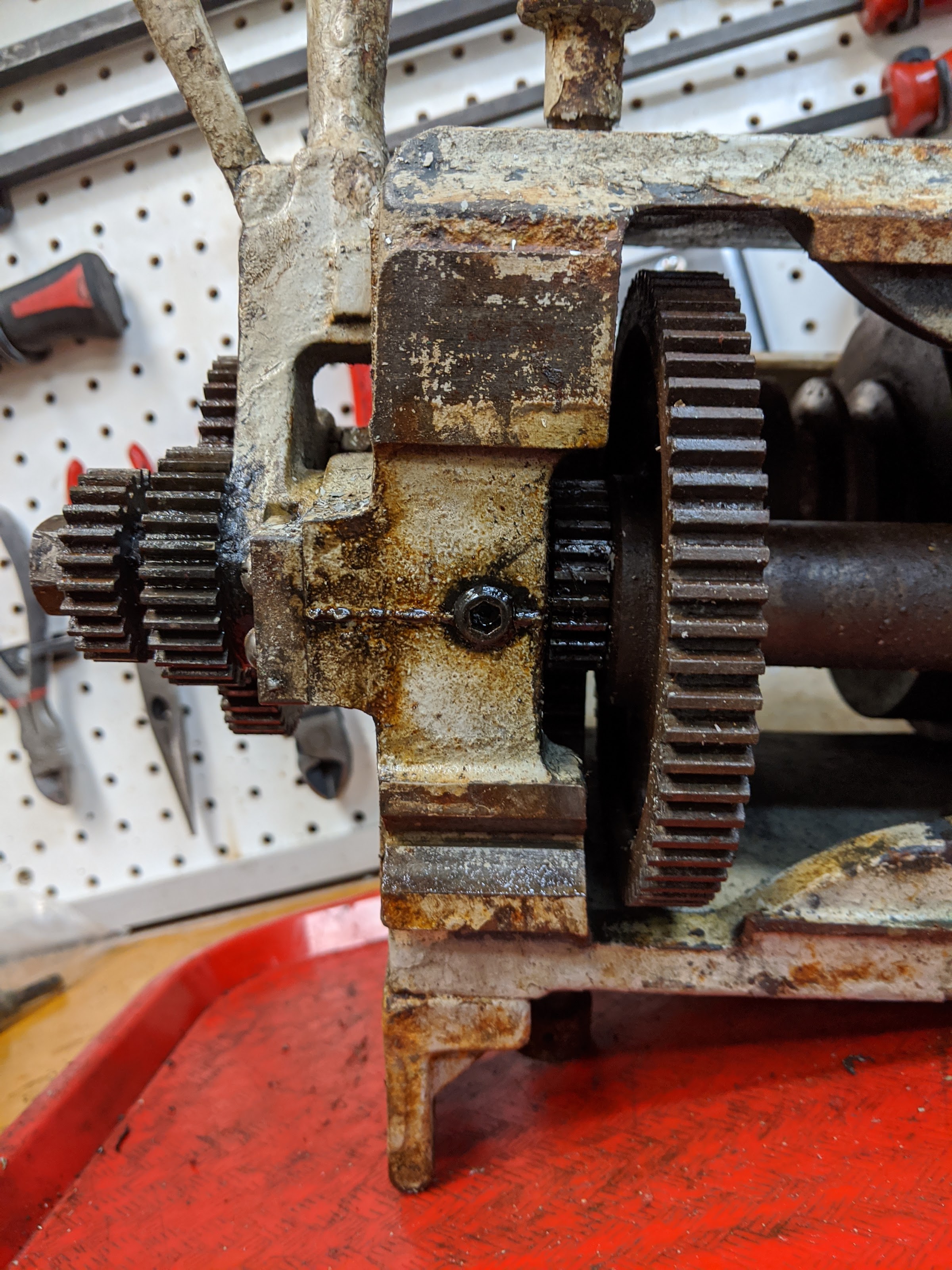
Does anyone have any pictures of how the head-stock is mounted to the bed? There are two bolt holes on the chuck side of the head-stock that look like they would clamp it to the bed with some sort of bar underneath. I don't see any provision for a clamp on the back side of the head-stock. The .pdf manual I found on Vintage Machinery seems to show mounting points on the front and rear.

Thanks for any help or guidance you can provide.
 
I can't give you any advise on the dc motor, but another option is a 3 phase ac motor combined with a VFD. The VFD (variable frequency drive) allows you to power a 3 phase motor with a single phase 220 V line, and also provides variable speed.
 
A treadmill motor should be adequate for most work. Control with rectifier and SCR controller

There should be a threaded hole in the front and back bottom of the HS and corresponding plates that fit under the lathe ways which are probably missing.

Any photos?
 
Just so that no one blows one up thinking that all VFD's are single phase input, that isn't true. They are made both ways. And some will run on either, with some de-rating if run on single-phase.
 
Re; the headstock, going by memory as I had an 825 some years ago. The chuck end has two bolts that hold it to a crosspiece under the ways, similar to the tailstock but not a sliding feature. These bolts are inserted from the top and screw into the crosspiece below the ways. The outboard end should have one threaded hole up into the headstock, so a bolt goes up from underneath, through the crosspiece, up into the headstock. Kind of the opposite of the chuck side. Cross pieces are just slabs of steel, maybe 3/8" thick.

Photo is from my 957, which I believe has a similar mount. Single bolt on the outboard end is actually a thru hole, not threaded. Maybe look through your boxes of parts for these pieces, or easy enough to make.

IMG_0098.JPG

Good luck on the stand. You might be able to rig up a couple of pulley options and then run 3phase thru a vfd to get most of your speeds in between. That machine has v-belts, I think, so you wouldn't have to deal with a v to flat belt conversion. Use the fenner style link belts. Won't be factory, but you can make your own speed chart.
 
Thanks for the help guys. I should have mentioned that I can't run a VFD since I only have access to 120v power in my garage. It's not ideal, but going to require some creativity on how to power this thing. I already have a fully functional 12" Atlas/Craftsman lathe that I can use to make parts for repairs. My plan is to sell off one of the two once I got both up and running. The Logan is nice that it's about the same size but probably twice as heavy and obviously built better just from the little bit of going over it that I've done already.

I've seen the ubiquitious treadmill motor postings that people have made, but didn't think that it would have enough power to make it worth while. It's cheap enough that it might be worth a try for initial startup. I'm happy to entertain other ideas.

For the mounting bolts, I appreciate the pictures you posted eeler1. The only part in the misc pile that looks like it works for mounting the head-stock is made of stamped sheet metal maybe 3/16 thick. It has the 2 holes that line up with the chuck end of the head-stock though. I will probably try and make some that look like what you posted. I will also flip the head-stock over again this morning and take a closer look at the other end.
 
There are VFDs made that take 120 volt input and give 220 volt 3-phase out. Or you could go the treadmill motor route for little money, if you find one cheap (or free!) With your other lathe you could make the pieces you need to adapt the motor to the Logan- with or without a countershaft arrangement
M

I didn't know that there were such things as VFDs made to run on 120v. My knowledge/experience working with larger AC power is limited. I guess it really comes down to the question if I would be able to get away with running directly from the motor to spindle with a small belt reduction or if a jackshaft setup is going to be required. The treadmill motors seem to run at about 6k rpm, so would require a significant reduction to operate. I've seen larger PM DC motors that run about 1800rpm at 90v DC. My understanding is that this would represent a constant torque through the motor speeds, but only the rated HP at top speed. If I could get a 2:1ish reduction from the motor to the spindle, then I would be in the correct ballpark for speed.

I just worked for a couple of hours breaking down the larger assemblies to find out what's missing/broken and have been pleasantly surprised. Most parts seem to be in fairly good shape. I've got the rusty parts soaking in a tub of evaporust. Here are some pictures of what I'm dealing with.

y3WbljeU6tGT0M9qsLcftUhPCSlHTp6fvg0lrPSw48t6ZU763cJ9Fhe-qUfvMbT8BAX3GA00GaQmS5fWftCd0cA7aiXwe6CPpd8tS5xgh2DEKgIqhnCVRvHcr012HgTspV6JwbQg5fk=w2400


Ap8VLttT1NOSSRVQVyf4ke-rSdARM0-4jgIqLkN7e9t1pFFiFMfxDdwSIa4UY7ksXtImYU1ByaJWqavUbU6ixed_JM2QrBA2pm8hOSFFYvXI6iGvla48aBoZg-zTOYjLYIPzIGp8oG0=w2400


Here are a couple of pictures from the bottom of the head-stock and the apparent "clamp".
KAMzxxM8m0rbmIK31uoAfY7bmAtowM1wOW_clD7Ub1o8hJim4oigbWc9_JyVddT6sChK3M7vHTPmOd9frzQ7XsvW5WFTyiaohmS96shbjytsim6FsF2iaXo0m-hiIVurj8WIfEHKnQM=w2400

1EJPP8-FkaGW0WwusbYZABvHYDb3InQTvI1-rIpVYVj9sRemOZDjt5IRfHd9pGOEI80Nhe3hpph7MSxpJS5nklJmfCsO5nywPR6oo4WsO5qtnt00uEFfKQiQuOu3TMVtU5-6VUrUyHk=w2400

f1dHv9Q_P7j9161_XZSiKzp72n9k5Tb7-a4k4O_zAKJGlsMTV4kyJgdTdCRY3azg2HCmyUNlkJW2WcwXJEWJtKK7jwZAsjeCiTBIRdtlgMLEoJ0vc_Bxta5bfoBrhBBGY5xnS95kuYY=w2400


I don't see anywhere on the back of the head-stock where a clamp would bolt through.
 
In our downloads section, there is a Logan 800 series manual and parts list. It shows a short set screw up inside the hole with a bolt threaded into the same hole.


IMG_0965.jpg

This is from my Logan 200 parts list, but it appears to be the same as the 800 series list. Part number 0322 is described as a Socket Set Screw, 7/16-14 x 5/16.

If I remember correctly, you have to level up to Gold Member status before you have access to downloads. Well worth it since it includes
the operators manual and parts list. You can also purchase that manual from Logan directly if you want.
 
And the winner is....


Nogoingback!
I would not have guessed that the set screw should be farther up into the casting and that another fastener would share the hole. I just went out and threaded that set screw much farther in and there is plenty of space for the additional bolt. I have the parts manual and other documentation from vintagemachinery.org for the 825 and that has been very helpful to identify the missing parts. Thanks for helping to sort that out. Now just make the plates and clean up the rest of this mess.

You wouldn't happen to have any creative solutions for powering this thing, would you?
 
Back
Top