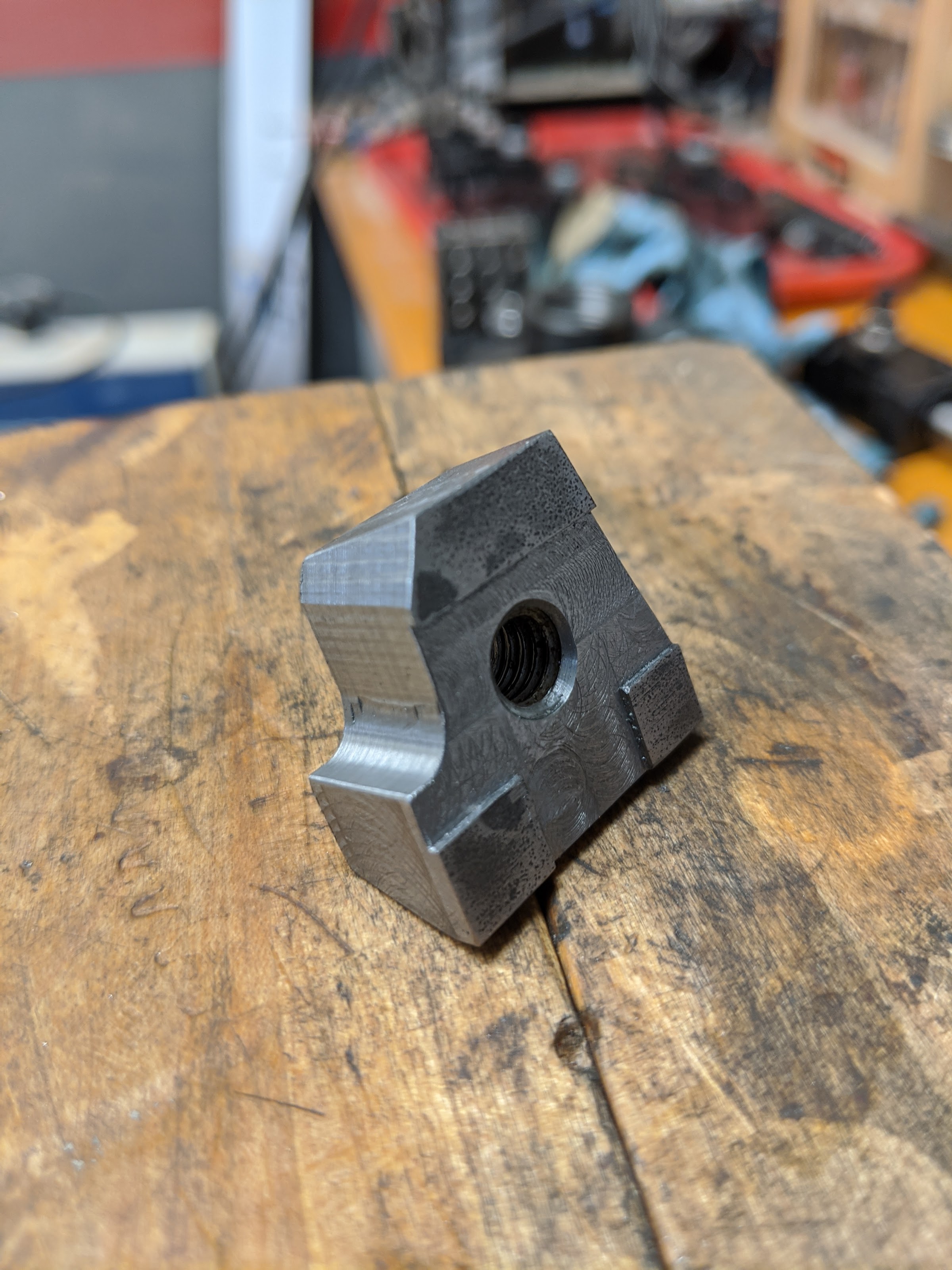
I do not have the dimensions although the thickness seems to be the only significant dimension as the length and cut out have plenty of room for movement. You could always do a wood prototype that would be easier to play with until you nailed the dimensions.
Last edited: