- Joined
- Dec 25, 2011
- Messages
- 10,508
I have four comments, other than that the ball bearings look good, but....
I am not familiar with this machine but if it has a multi-step conical pulley on the spindle and a pin of some sort that locks that pulley to the bull gear for direct drive and the pin is pulled out and the back gears engaged for back gear, the the lubrication note should be to also lubricate the pulley bushings every time that you lubricate the back gear bearings or bushings. The second is that the lubrication frequency should be monthly PLUS whenever the back gears are used, not just whenever the back gears are used.
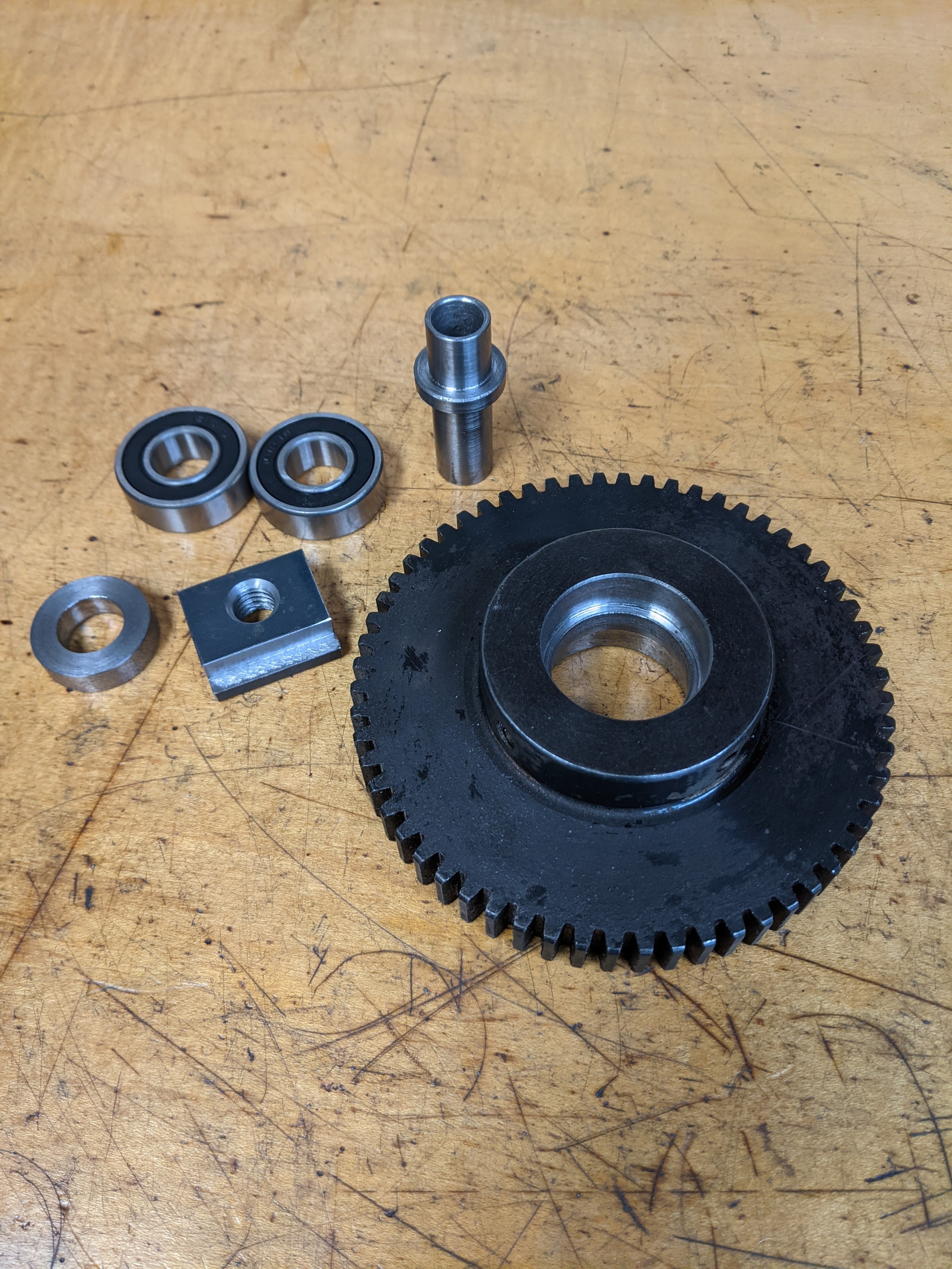
The third is that whenever you switch from bushings to ball bearings on the Tumbler, the bolts or pins must lock the inner races of the ball bearings to the tumbler. Else Murphy's Law generally guarantees that the bearing inner race will tend to spin on the bolt/pin instead of the outer race spinning on the inner race. And prematurely wear out both bearings and bolts/pins. One way to fix it is to insert an inner race shim under the head that is thick enough to lock up the bolt/pin and inner race.
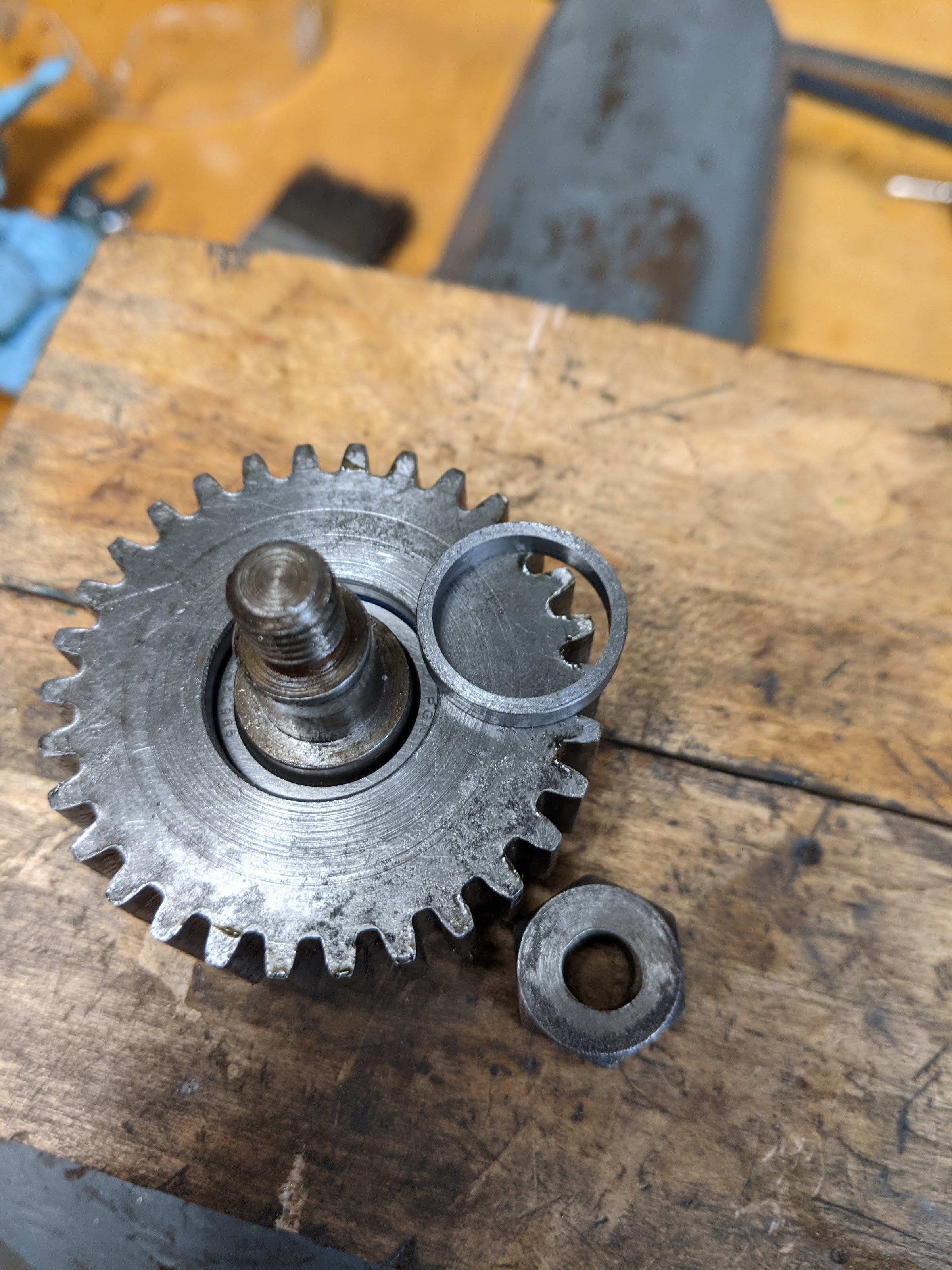
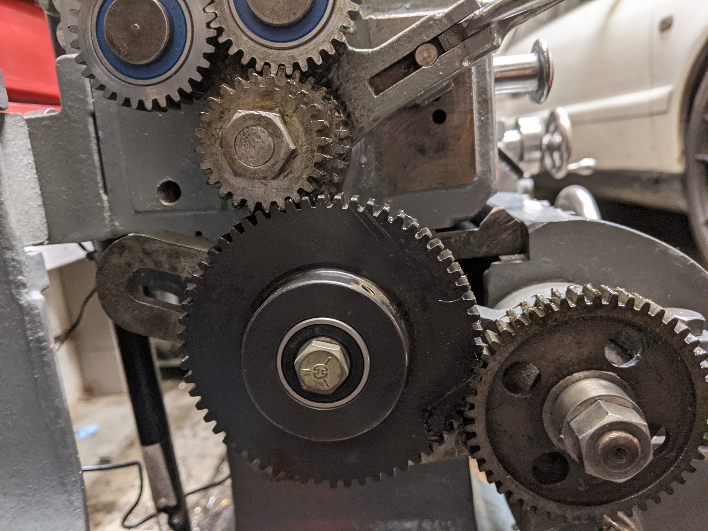
The fourth is that the photo above shows what appears to be a compound gear, one of which is presumably the 60T gear that you mentioned. You cannot simply replace the keyed bushing with two ball bearings because what you will end up with are two independent idlers. If the input is to the larger gear and the output from the smaller gear, the lead screw will not turn under load. There are several ways to fix this including installing new but otherwise original parts.
I am not familiar with this machine but if it has a multi-step conical pulley on the spindle and a pin of some sort that locks that pulley to the bull gear for direct drive and the pin is pulled out and the back gears engaged for back gear, the the lubrication note should be to also lubricate the pulley bushings every time that you lubricate the back gear bearings or bushings. The second is that the lubrication frequency should be monthly PLUS whenever the back gears are used, not just whenever the back gears are used.
The third is that whenever you switch from bushings to ball bearings on the Tumbler, the bolts or pins must lock the inner races of the ball bearings to the tumbler. Else Murphy's Law generally guarantees that the bearing inner race will tend to spin on the bolt/pin instead of the outer race spinning on the inner race. And prematurely wear out both bearings and bolts/pins. One way to fix it is to insert an inner race shim under the head that is thick enough to lock up the bolt/pin and inner race.
The fourth is that the photo above shows what appears to be a compound gear, one of which is presumably the 60T gear that you mentioned. You cannot simply replace the keyed bushing with two ball bearings because what you will end up with are two independent idlers. If the input is to the larger gear and the output from the smaller gear, the lead screw will not turn under load. There are several ways to fix this including installing new but otherwise original parts.