Seeking Advice on Atlas No. 700 Taper Attachment

On the one I have there is a normal full dovetail on the guide bar.

A = .2765 according to my surface plate and Starrett digital height gage...... sorry if all the pics are frustrating you.

Last point of clarification, the top surface of the rear arm of the clamp (the part with the slot) ends up 0.2765" ABOVE the lathe bed when installed? Is that right?
 
Ok. I finally saw what the dovetail looks like on the bottom of the guide bar. It is just barely visible right at the bottom of the first photo in Post # 12. The guide bar is quite a bit thicker than I thought. And my comment about the female dovetail on the bottom of the bracket being incorrectly drawn was correct.
 
Yes


Sent from my iPhone using Tapatalk
 
Well, I still don't know for certain whether the gib sits straight up and down like the carriage gib on any Atlas lathe does or laid over at an angle like the cross slide gib. But the front edge of the 10-702 Guide Bar is straight up and down, cut at 90 degrees to the top and bottom. So the 10-701A Bracket probably only has half of a dove tail, cut on the back side.

What are you talking about. I have read this several times and am completely lost. The only gib on the entire setup runs parallel to the bed and is along the outermost edge of the bracket.


Sent from my iPhone using Tapatalk
 
I think what he's referring to is this here:

Untitled.jpg


In the drawing it looks like the rear face of the dovetail is straight vertical while the other one is the standard 30* angle that we've come to expect.

The drawing is not super clear on that but the guide bar does indeed have an angled face on each side, like a normal dovetail.

And thanks again @Moderatemixed for the clarification. Maybe these dimensions aren't even all that important to the function but I wanna be as close as is reasonably possible to the original.
 
825160240cdfc5bdc6e7a4a5e998e23c.jpg
1d1550ff8ce510621a029198d5235689.jpg
135359ba0b42bc51481230783783d28c.jpg
d7acf0dcc16fc72b67636feec52cf614.jpg
a66b64e486899df5c6bfb640e278ae64.jpg
b7426a4fbb2d01c3f5b37ce6c4da1135.jpg
876c8ef157020e736cac2834fa2ca2bd.jpg


Sent from my iPhone using Tapatalk
 
Hopefully that helps clear it up.


Sent from my iPhone using Tapatalk
 
So once you get it all put together you have to show me how to use the darn thing...... I’ve never had it on my lathe or used it. (But I am going to). I just picked up an Atlas horizontal mill and I need to make a 1” arbour for it. I need to turn an MT2 on one end of said arbour. This thing should be just what the doctor ordered.... or at least I hope it is.

Let me know if you need anything else.

Derek.


Sent from my iPhone using Tapatalk
 
It might be a while til mine is up and running but the PDF attachment in the first post has the mounting and use instructions.

Doesn't sound too difficult. It's covered in the first page of the PDF. Check it over and see what you think.
 
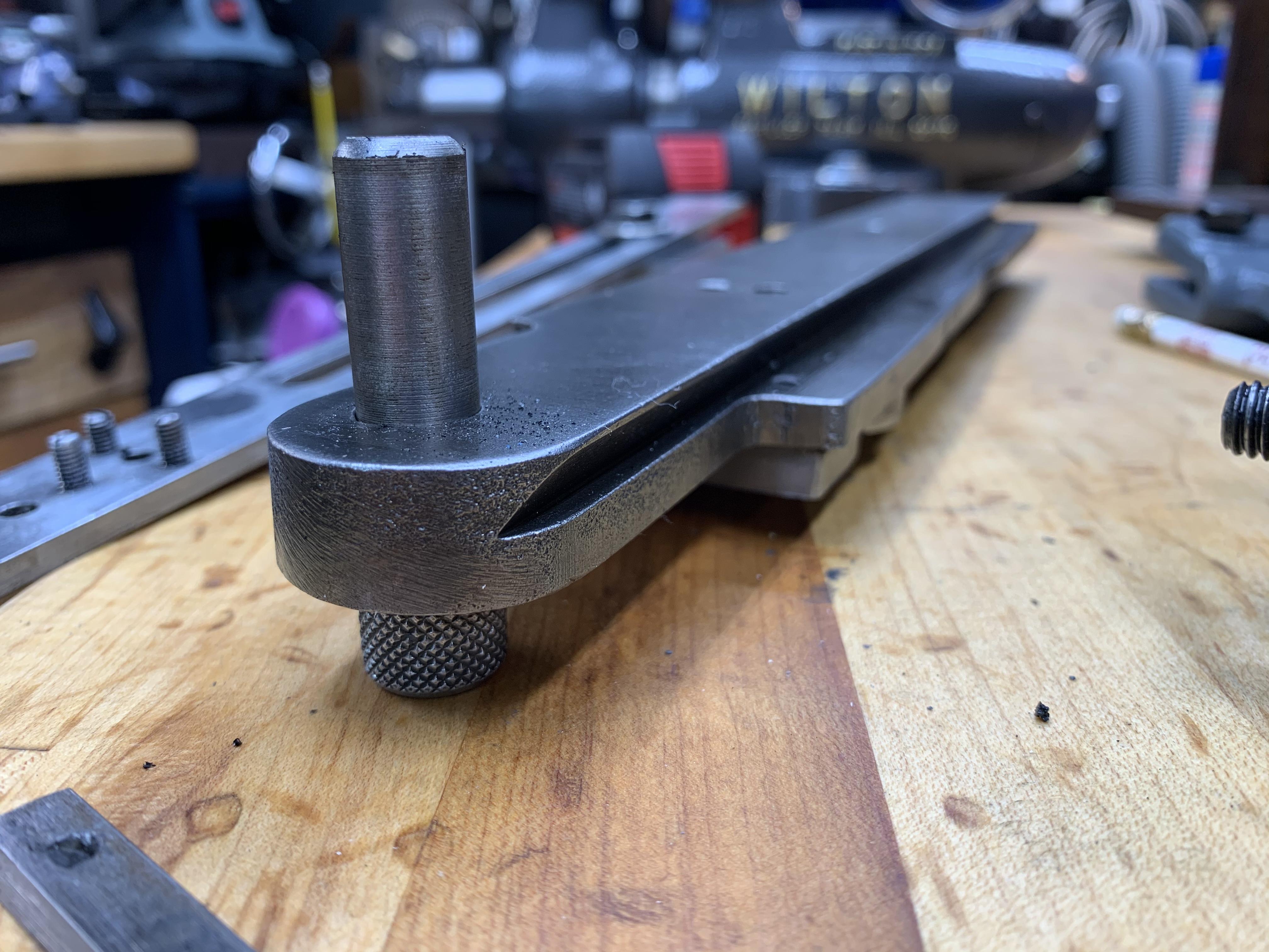
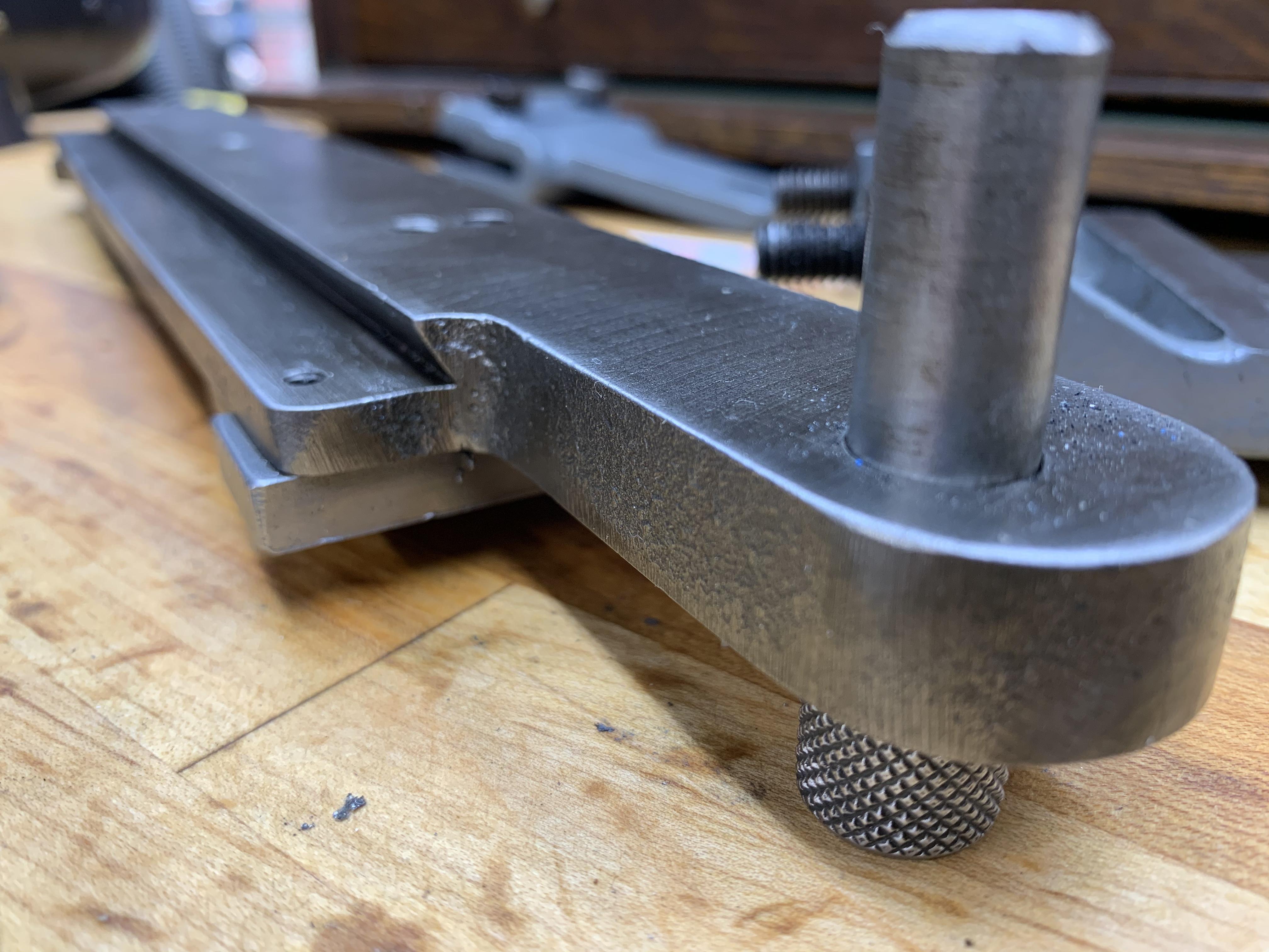
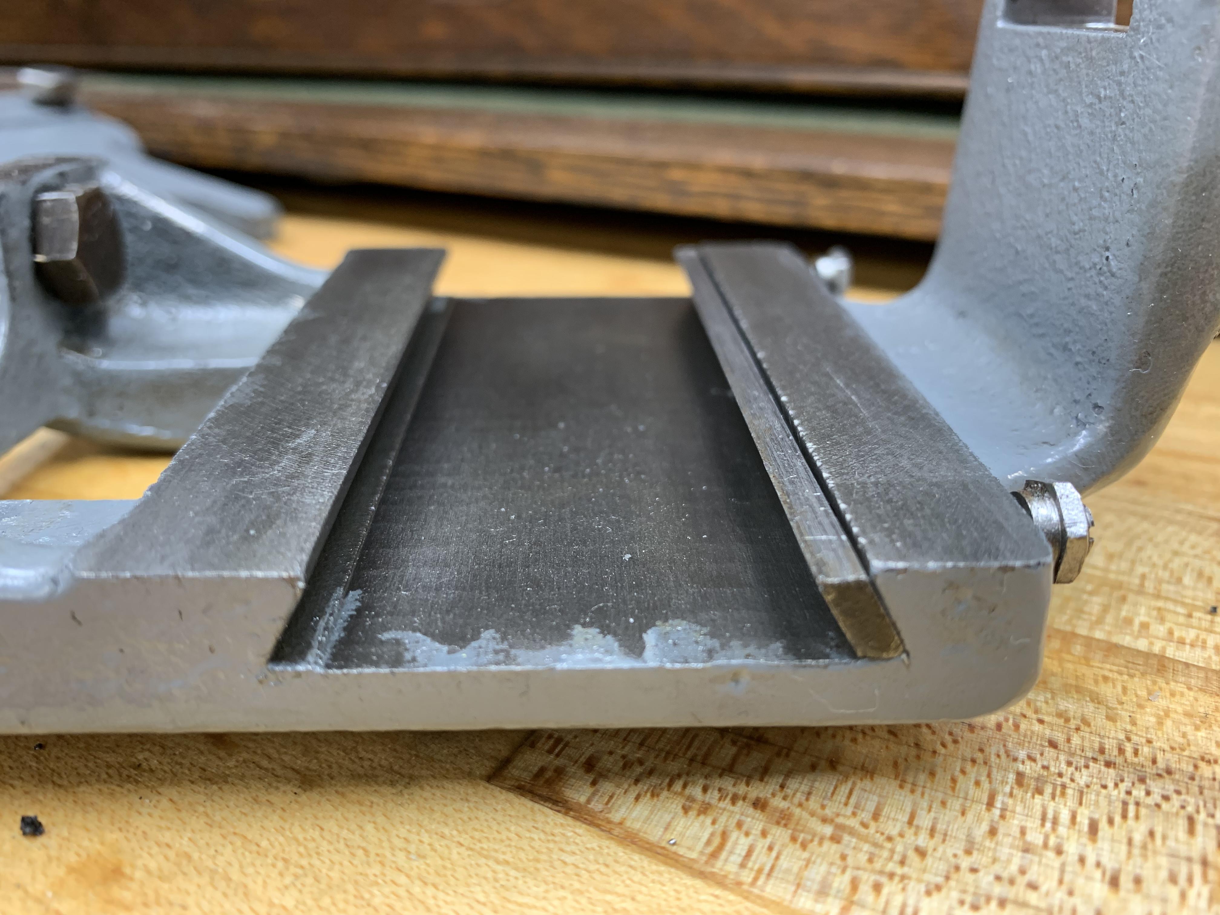
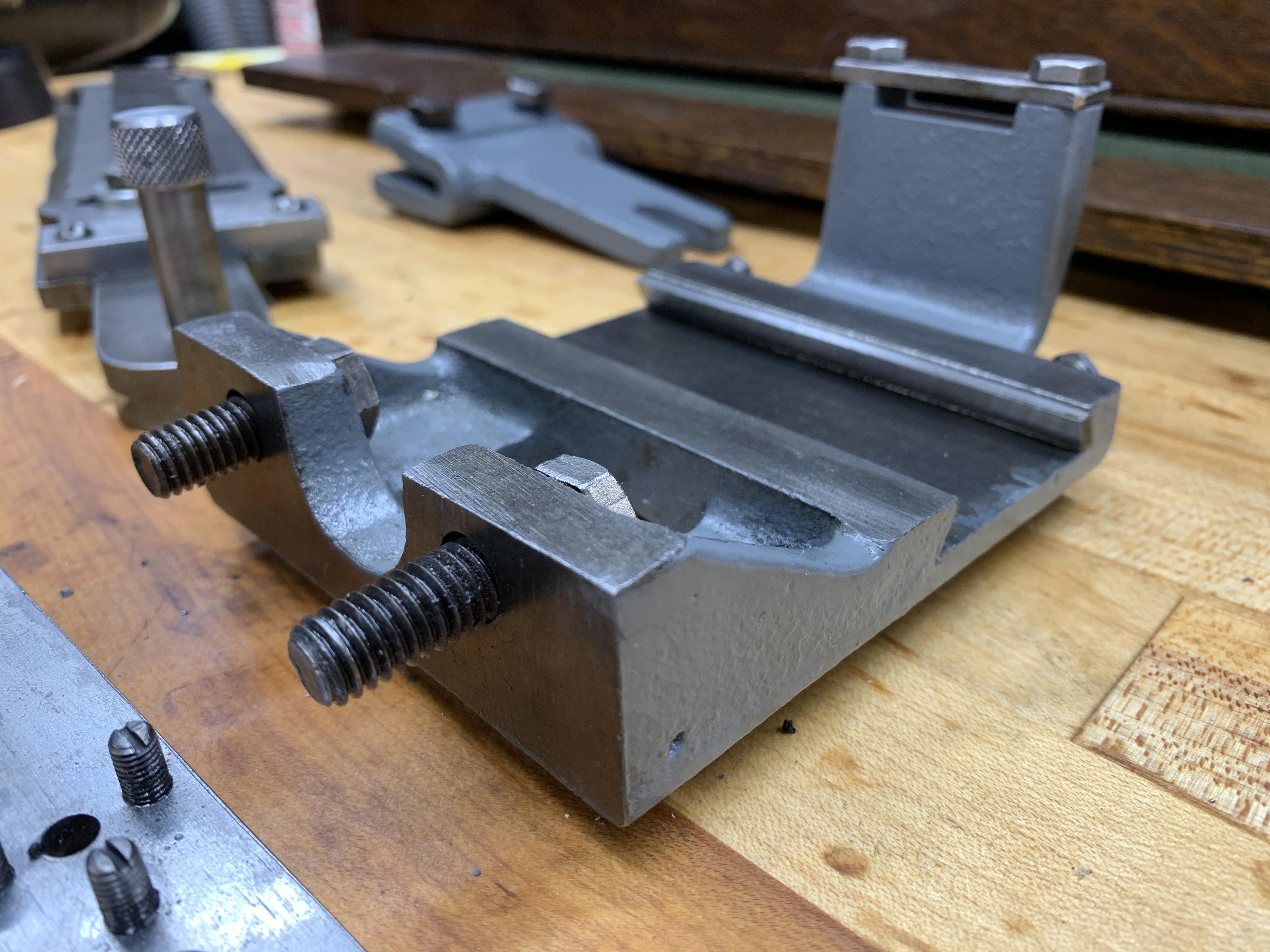
OK. The most recent batch of photos answered my questions. The drawing in the manual copy of the right end of the guide bar is wrong as your first photo in this series shows that the dovetail on the bottom of the (inverted in the photo) guide bar should be clearly visible as it extends out all of the way through the radiused right end. And the drawing of the tailstock side of the Bracket is wrong. As drawn, the near (to the operator) line representing the front edge of the right end of the dovetail is drawn too close to vertical. It should be laid over more to the right. But now that I know that the dovetail should be visible on the front of the handle on the right end of the guide bar, I probably wouldn't have questioned the bracket drawing.

Also, there are two other errors in the text part of the instructions for installation and use of the 700 Taper Attachment. As with the 760 and 6822, Step 1 for installing is to remove the chip guard and attachment screw from the rear of the cross slide. Step 2 is to remove the cross feed brass nut and its attachment screw. Then proceed with the rest of the installation instructions.

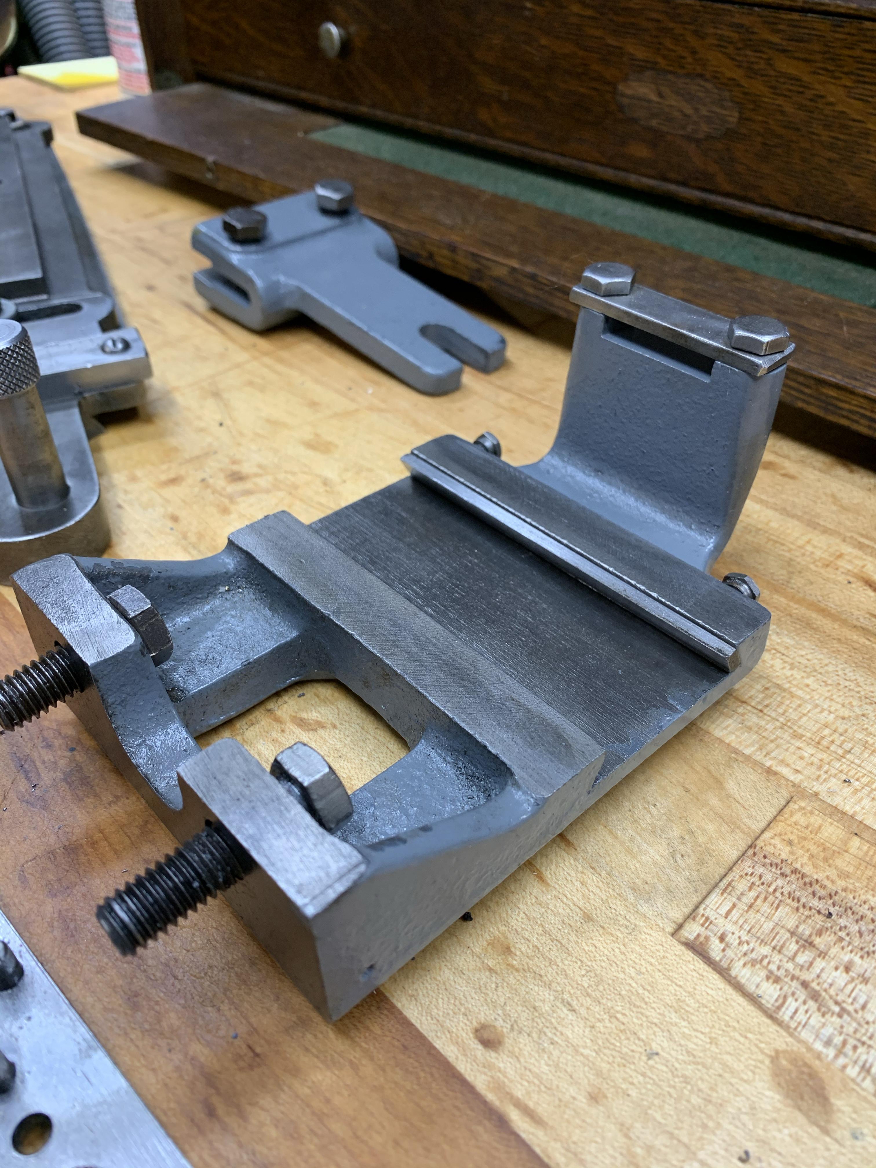
The 10-24 x 1/2" round head mach. screw shown above the left end of the draw bar goes into the hole formerly occupied by the chip guard. Tighten it after installing the pin through the draw bar and into the hole formerly occupied by the cross feed nut and adjusting the three 10-32 x 3/8" set screws. After tightening the screw but with the screw for the 10-704A Slide loose, confirm that the cross slide and draw bar move freely across the carriage. This is your coarse adjustment of where cutting is going to take place. After tightening the bolt through the draw bar into the 10-704A Slide, all further adjustment will be done with the compound feed. The compound slide should be set to 0 deg. and if you are using either a QCTP or a 4-way turret, they should be square with the lathe axis or with the piece of solid round that you usually start with.

One further tip - before starting the installation, check and if necessary adjust the carriage gib screws.
 
Back
Top