[How do I?] Seeking Assistance With Jig-machine Build

I'd be concerned with the "overhung load" imposed on what you call the X axis rail.* If you're cutting a drum that's 16" deep, that's a very long lever arm. I don't know what kind of downward force the cutter would impose on the end of the arm, but it would be good for you to at least work up an estimate based on your experience. Then study the specifications of the linear rails carefully ... maybe go up a size or two. Using two rails next to each other would give you about twice the stiffness ... but using a "taller" rail (especially with an increased vertical distance between the ball races) could increase the stiffness even faster.

*Note on axis nomenclature - What you're calling the X axis is generally known as the Z axis in machine tool parlance. What you're calling the Y axis is called X. No great shakes, as I'm pretty sure I understood what you were saying. But if you plan to do a lot of discussion with machinists, using the right terminology will help avoid confusion.

Thank you, very helpful. my X, Y and Z references are from limited milling machine use. I always thought that Z was up and down, regardless of machine type! thanks for the correction.

I have been concerned about the boring bar overhang, and will likely start with no more than 10 inches.
 
Since you've got a minimum of six or seven inches inside the drum I suggest that you extend the platform into that space and mount rails on it for the live tool that Tony suggested to ride on. 22" isn't too much overhang for a 3" by 6" beam. Do likewise on the outside opposite that tool. Then build a U-shaped carriage for the tools to ride on so that both sides are cut at once at the same place by tools rigidly mounted to the same structure. With live tools you might be able to do full-depth cuts, eliminating the need for the cutters to move in the X direction. Drive and control the cylinder with rollers.
 
Since you've got a minimum of six or seven inches inside the drum I suggest that you extend the platform into that space and mount rails on it for the live tool that Tony suggested to ride on. 22" isn't too much overhang for a 3" by 6" beam. Do likewise on the outside opposite that tool. Then build a U-shaped carriage for the tools to ride on so that both sides are cut at once at the same place by tools rigidly mounted to the same structure. With live tools you might be able to do full-depth cuts, eliminating the need for the cutters to move in the X direction. Drive and control the cylinder with rollers.
Now that's something I never considered. what a great forum! I am somewhat concerned about smoothness of the finish using live tooling. what sort of bit is recommended ?
 
Now that's something I never considered. what a great forum! I am somewhat concerned about smoothness of the finish using live tooling. what sort of bit is recommended ?

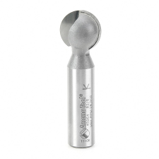
The tool bit for live tooling would depend on the material you are cutting. If you are cutting with a router, then a lollypop bit would proabaly be the best because you will have to set the motor at an angle for clearance.

upload_2016-11-14_8-8-13.png

Rigidity is going to be the key to minimize chatter. I would use only 1/2 inch shank, solid carbide or carbide tipped bits.
 
Shell material might be maple, oak, ash. Many different species, including some multi species. The raw shell has 20 staves, so there is no opportunity to cut it to a perfect circle before glue-up.
You would glue the staves around a mold of the correct ID. That would control the ID. Then you would only need to address the OD to size.
 
I'm going to go a different direction from Jim. Seems to me that the rigidity issue would be more of one where the flexibility and instability would come from the work rather than the tool. I would build using a smaller router, but still on as stiff a support as possible, and use a small round bit. Of course this will take longer to do the job, but that's just the way I would approach it.

I do like John's idea of doing both the ID and OD at the same time. That gives a balance to the cutting forces that would be hard to achieve any other way. You might need to consider some means of adjustment for "wall thickness", for lack of a better term. It might be done in one pass, or might give better results with a heavy roughing pass and a much lighter finish pass.
 
The tool bit for live tooling would depend on the material you are cutting. If you are cutting with a router, then a lollypop bit would proabaly be the best because you will have to set the motor at an angle for clearance.

View attachment 139371

Rigidity is going to be the key to minimize chatter. I would use only 1/2 inch shank, solid carbide or carbide tipped bits.

Maybe a bearingless chamfer bit?

I assumed that the cutters would be mounted on shafts parallel to the axis of the drum and driven by one or more motors mounted clear of the drum. The shafts would need good bearings on both sides of the cutters.
 
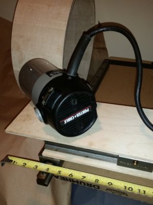
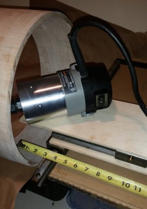
Thanks for all the excellent replies! I mocked up the setup shown in the pictures using some thin plywood. My router is 1 3/4 HP which can use either 1/4 or 1/2 inch bits. Much to my surprise, there is enough reach. I can get the router body very close to the shell.

The idea of cutting both ID and OD simultaneously does not appeal to me. The OD can't deviate from 13.875 inches. In my experience, best results are achieved with a very fine final cut. This will minimize sanding. Also, the thickness may differ from one shell to the next.

This set up uses 4 rails with 2 bearing blocks on each. Notice that the overhang (directly under the router) is approximately 9 inches. I can get another inch of reach at the router bit end. To cut a deeper shell, the bearing blocks would need to be closer together. Right now, they are about 10 inches apart (not shown in the pictures).

Questions:
-Can I put the bearing blocks closer together on the top platform to get more reach? Any minimum distance between the blocks?
-Each axis will have a metal plate/platform. What thickness should they be? Should I use aluminum or steel?

Appreciate any additional thoughts/advice.

Thanks

Jim


live Tooling 2.jpg Live Tooling Router.jpg
 
You would glue the staves around a mold of the correct ID. That would control the ID. Then you would only need to address the OD to size.

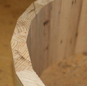
Here's a raw shell before cutting. Both interior and exterior need to be smooth and flat.


Staves.jpg
 
Back
Top