Semi-automatic parts weighing/counting machine.

Let me guess, knock in some dowel hole for locating pins with your CNC to pick up edges to locate the part, then clamp? Pick up the corner at the bottom right with a dowel pin on the horizontal and vertical, and a third pin to pick up the face on the surface at the upper left? I'm on pins and needles! Not literally, but I'm always looking for clear ways to secure and locate oddball parts.

Bruce
If I were going to be making a number of these, then that then that is exactly what I would do. But since this is a 1 off, there is an easy way to do it.
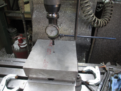
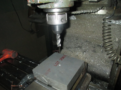
my guess is that you have what looks like a 90deg corner at the bottom (last picture). Seems you could locate X and Y from those two faces.

That would work just fine. Would require dialing it in then locating the corner.

But when you have a CNC mill life is easier :grin:

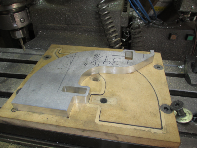
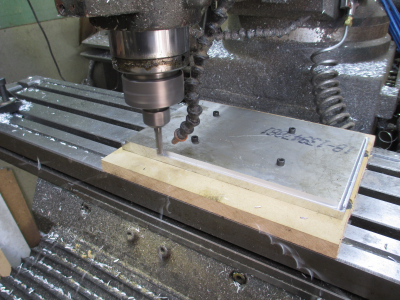
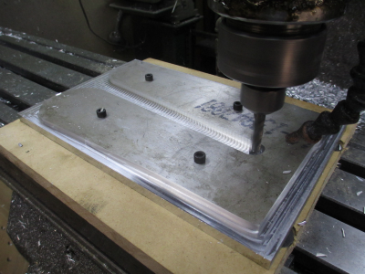
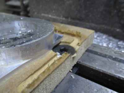
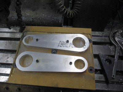
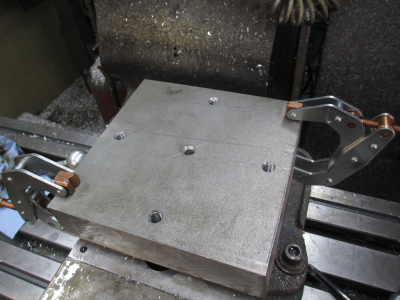
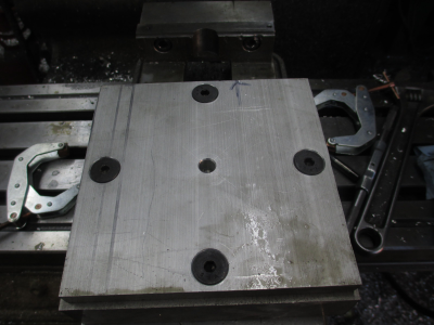
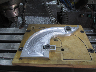
In the last picture above you'll notice the circled divot on the lower left. That is the 0,0 point for the next operation. This part was completely ''machined'' in my head prior to making any chips. The spoil board was actually drawn out and the holes located to fit when I flipped the part over. The part itself was also designed to fit the T-slots on my mill for hold down. All of the holes in the spoil board were drilled from the drawing. The two circled holes will be used in this operation. There are T-nuts already staged under those holes.
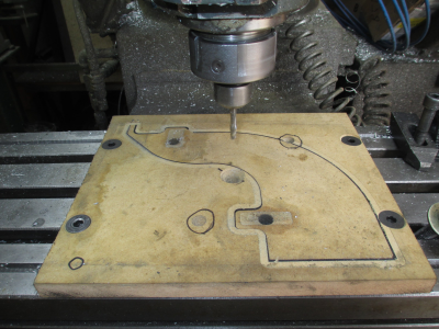
1614733449662.png


Then set the 0,0 point, pretty close is good enough, does not have to be exact.
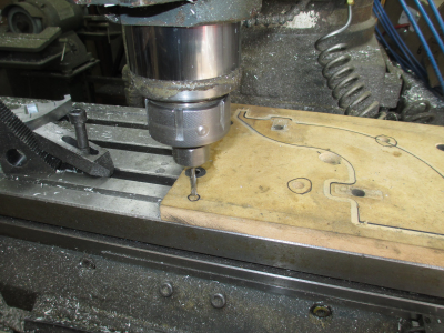
1614733476899.png

Then I took a light profile cut just to get the outline to make sure I wasn't going to crash a tool bit into a bolt head.
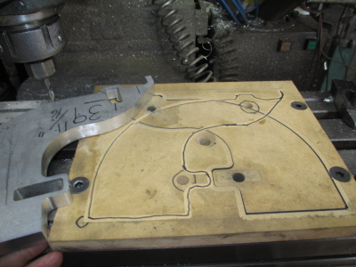
1614733503530.png

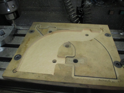
Then pocket out the shape, 0.250 deep.
1614733527499.png

Still a little too small by design, about 0.008'', so adjust the tool offset in the CAM program, and run another finish pass. When finished, it was a light press fit. The MDF has some ''give'' to it so you can make things pretty tight. Most likely did not even need the hold down bolts, but I'm a belt & suspenders kinda guy. :grin:
1614733548710.png

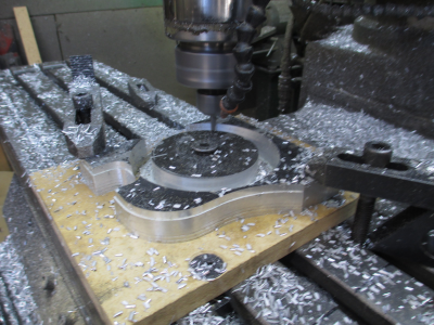
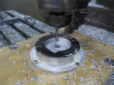
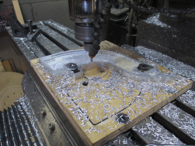
Then on to the fun, piles of aluminum chips.
1614733577336.png

And finished. It was a bit of a PITA to get it out of the pocket, I forgot to put a screw driver access point to pry it back out, but I managed to use one of the corner clearance holes to get a bite on it with a screwdriver.
1614733606005.png

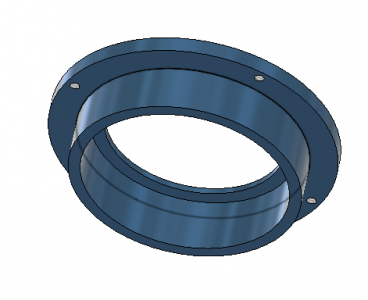
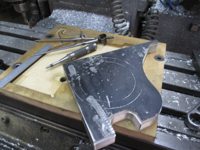
So on to the next part..... The Upper Rotor Bearing Housing. 4.5'' at maximum OD, 1 inch thick aluminum.
1614733726634.png

And shown in place
1614733680156.png


And I can get it out of one of the cutoff pieces from the Prox Bracket.
1614733633975.png

But that is a project for tomorrow. I put in my 4 shop hours today, so it's time for a sandwich and a nap. :faint: That's the nice thing about being retired, I can quit when I want. ;) I will get the tool paths worked out this evening however.

More later.........
 
Last edited:
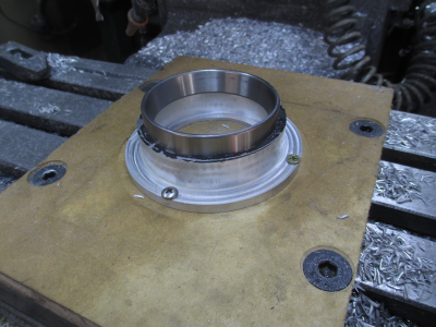
OK, on to the bearing housing.

First relocate 0,0, centered on the center T slot. Note the high precision method of doing this. o_O It just needs to be close so I can get a bolt in a T nut.

1614829430046.png

Drill and mount the new spoilboard then start chewing away anything that isn't the part. The clamps are there just to keep the scrap pieces under control when they are cut loose from the part. I could have used a bigger end mill, but the 1/4 was already in the collet.

1614829633141.png

So time to work on the center pocket. Just held with screws into the spoilboard.
1614829857178.png

And finished. The bearing is a light press fit, I could almost push it in by hand. All I have to do is heat the housing a bit and drop the bearing into place. The OD finish is not up to my normal standards, was getting a little chatter in that long skinny endmill.

1614830014608.png

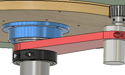
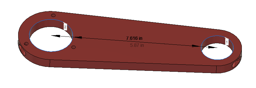
So the next pieces are the motor mount arms, 2 pieces required. 1/2'' thick aluminum.

1614830326905.png
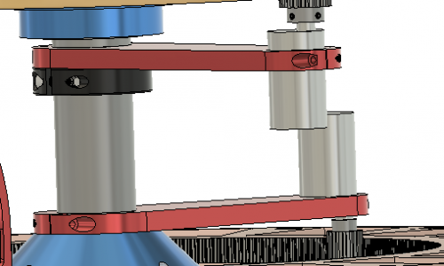
And in the assembly.

1614830540672.png

I'll get these done tomorrow.

Stay tuned......
 
I could have used a bigger end mill, but the 1/4 was already in the collet.

Jim, does this mean that you are not using a CAM system to develop the G-Code? Or are you writing G-Code on the fly? For me, I need to specify the cutter that I will use when I do the CAM work and it would be much easier to change out a cutter than to go back to the CAM program and change the cutter there. As I am typing this, I also thought perhaps you are just editing the g-code to change the Tool Offset. Is it that simple?
 
Jim, does this mean that you are not using a CAM system to develop the G-Code? Or are you writing G-Code on the fly? For me, I need to specify the cutter that I will use when I do the CAM work and it would be much easier to change out a cutter than to go back to the CAM program and change the cutter there. As I am typing this, I also thought perhaps you are just editing the g-code to change the Tool Offset. Is it that simple?

Most of the time I post the G-code from the mill computer, and many times do the CAM work there also. So I look at what tooling is setup in holders and just enter that tool(s) in CAM. I should note here that when I'm making parts, I have Fusion 360 running on the mill computer so I have the part model right in front of me. Pretty easy to change the tool in CAM and re-post, only takes a couple of minutes.
 
Got it. My setup is not nearly as efficient as my CAD and CAM system is on the second floor of the house and the CNC Mill is in the detached Shop. Might look at changing this once I retire.
 
Ok I didn't get them done ''tomorrow'' as I said in my previous post.... It was cold in the shop :eek: But I did get them done today.

1615445442236.png
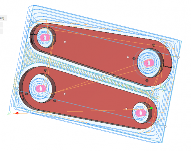
So cut a spoil board and get it bolted down, center the workpiece on the table, drill the hold down holes and start removing anything that isn't the parts. The 1/4-20 cap screw holes are just tapped in the MDF, works surprisingly well, I used screws that are long enough to nearly go all the way to the table to get maximum hold.

1615445605926.png

Starting to take shape. 3000 RPM, about 300 FPM, 3/8, 3 flute aluminum cutting end mill, 16 IPM feed, 0.170 step over, 0.250 DOC.

1615445897133.png

Now here is where the fun begins. See that slot in the spoil board? Well that is not supposed to be there, the end mill was 1/8'' too deep on the last step down. :faint: The end mill passed over the hardened bolt head with a couple thousanths to spare, I got lucky.o_O I changed the material thickness to fit the stock I had on hand, and forgot to tell the CAM program to expect 5/8 material and not 3/4 material. The good news is that I was there and quickly dropped the knee 0.125'' and let the cut continue. Had it reached the next bolt head the end mill would have hit that one, it wasn't sunk quite as deep as the others.

1615446692969.png

And done. 108 minutes later. It just kills me that I have a perfectly good Haas mill sitting on on the other side of the shop, and I'm barely qualified to hit the E-stop button on it. The Haas would have chewed this out in about 15 minutes or less. 6000 RPM spindle, 7.5 HP, 400 IPM rapids, and could have cut this in one pass at 120 IPM feed. I'm going to get young son to teach me how to run it.

Then the other minor problem, the small holes are supposed to fit the motors I have, well somehow I plugged in the wrong diameter for one of them into the CAD program so one of them is 0.050 large. I can shim that, but it's irritating. :mad: This is what happens when you don't double check things. Once you press the go button, the computer is just going to do exactly what you told it to do.
1615448566220.png


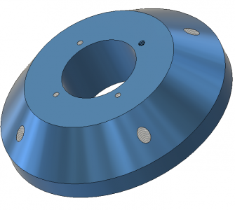
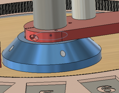
So tomorrow is the center tube support bracket. This was supposed to be 2'' high, but I couldn't find any 2 inch thick material, I thought I had some on the shelf, but could only find 1.5'' thick, I could have sworn I had some 2 inch thick material out there. So I'll make it work anyway.

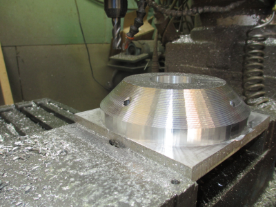
This looks like a lathe job, but just for fun I'm going to do it all on the mill because I want experiment with surface finishes when cutting that large chamfer.

1615447848833.png
1615448092963.png

More later.....
 
Last edited:
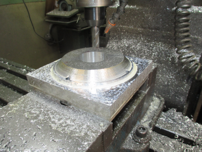
It just kills me that I have a perfectly good Haas mill sitting on on the other side of the shop, and I'm barely qualified to hit the E-stop button on it. .............. I'm going to get young son to teach me how to run it.

From here it looks like this old dog knows so many tricks that teaching him a few more shouldn't be too difficult.

-brino
 
OK, I got a start on the tube support

This part is going in the vice. There are a couple different ways to make this on the mill. One would be machine the bottom side first; Drill & tap the holes, pocket the 2'' center hole, and finish lower OD. Then flip is over, center the part on the center hole, and machine the chamfer & drill & tap the top holes. But, the large OD is 6'', and without modifying my vice jaws, the 6 1/4 square raw stock won't fit. I thought about doing it this way, no big deal to modify the vice jaws, and make two edges parallel (the block was rough saw cut). But I decided to do it the other way, by screwing it down to a plate. The amount of work involved is about the same.

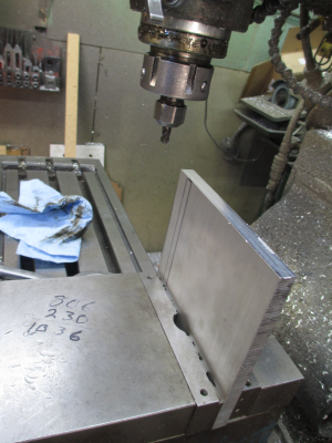
So cut a 0.5'' thick aluminum plate 6'' square, and square up 2 edges parallel to each other so the vice can get a grip on it.
1615598445817.png

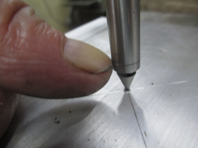
Mark the center and center punch. This only needs to be close. Then using the pointy end of the edge finder, locate the center using the fingernail method...... Move around until you can't catch a fingernail on the edge in any direction. This is now 0,0. Drill & C-sink for the mounting screws.
1615598784563.png

Then center up the workpiece and clamp it in place. Drill & tap for the mounting bolts, and drill a center hole to indicate to so that center can be located when flipped over. Since these two operations were done in the same setup, the mount holes and centers lineup perfectly.
1615599078792.png

Now bolted together with flat head cap screws. The arrow keeps me from getting confused, points toward the fixed jaw. Saves making stupid mistakes.
1615599228670.png

Then flip the assembly over and tighten the vice, smack down with a dead blow hammer and center on the hole.
1615599414055.png

Then try to find an endmill that has at least 1.5'' flute length. Originally I was going to use a 1/2'' endmill but I couldn't find one with that much flute length, I finally found this 5/8, 3 flute carbide, aluminum cutter. (I need to buy a few more endmills, my stock on the common sizes is getting low) One problem, it that it has a straight shank, and that tool holder wants a Weldon shank for a single set screw, and I don't have a collet for a 5/8 endmill. This is a recipe for disaster, because without the recess in the shank, the only thing that keeps that endmill from pulling out of the holder is the friction of the set screw. :eek: o_O The pucker factor was high for the first few cuts. The good news is that it held, but I did adjust the cut depth and stepover to ease the pull out force on the endmill.
1615599990979.png

About 90 minutes into the roughing cut
1615600361425.png

And roughed out, 138 minutes. 400 FPM (about 2500 RPM), 10 IPM feed, 0.25 DOC, and 0.180 stepover. The faceting is normal for an adaptive roughing cut, it is not supposed to be smooth, I left 0.040 for finishing.
1615600619146.png

I was going to make the finishing cut today, but Fusion 360 CAM was was arguing with me about the tool path to clean up the chamfer with a ball end mill so I decided to shut down for the day and retire to my desk computer to get this worked out. It was about quitting time anyway, I put in my 3 shop hours for the day. :grin:

More later.........
 
Back
Top