Shaft end drive dog

AGCB97

H-M Supporter - Diamond Member
H-M Lifetime Diamond Member
Joined
Apr 22, 2016
Messages
965
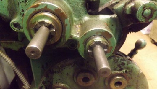
I'm building a case gear assembly for my Springfield lathe so I can cut metric threads. I need to cut a 5 spline drive dog on the end of a shaft. I have an idea how to go about it but not the technical specs. Here is a pic of one I have (have set of 3 ] 2-1, 4-1, 1-1). If you could point me to some specs or video of this operation or just a explanation of how you would do it that would be great. I have a dividing head and mill.
Thanks
Aaron
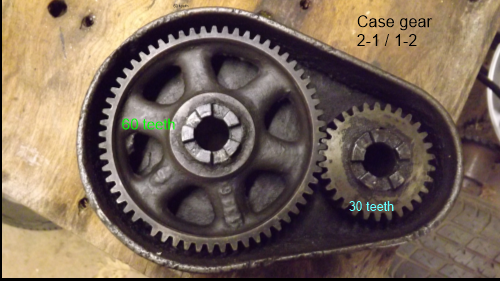
2 to 1 case gear.png
 
I'm thinking I would set up rotary table for 10 divisions and line up left edge of tool with center. Do 5 cuts 72 degrees (2 divisions) apart. Then advance table by 36 degrees(1 division) and line up right edge of tool with center and make 5 cuts. Tool must be smaller than inside dimension of one dog tooth.
 
IFRC Tubal Cain, aka Mr. Pete, used a similar setup when making a device to allow use of an electric drill to power the knee on his Bridgeport mill. He gave a pretty good explaination of the process.
 
Be careful. In the pics I can see that the cuts are not radial, i.e., not pointing toward the center, and also not parallel with each other. The piece will have to be offset by some amount to get that angle correct on the cuts, and will be reversed on both sides of the teeth. I am not sure of how to do that without the factory specs beyond using something like a 6" machinist scale held against a tooth and then lined up by eye with the table slots, and then measuring the offset from center, which is probably close enough...

Edit: If you look in post #3 above, you will see that the one tubalcain made appears to have the angle of the cut going to the other side of center.
 
Are you planning on this being 1 piece as in you cut into the shaft itself or is this going to be a second piece that is pinned, welded, epoxied, soldered onto the end of the shaft? In either instance it looks like you therr was a sizable investment into making these gears which makes me wonder if you plan for a sacrificial piece to go between incase mr Murphy visits?
 
I have cut clutch teeth like that with a slitting saw or side milling cutter, yes, the cuts are radial, and the same setting of the saw (with one side of it on center) will serve to cut all the teeth, going completely across the part, its simpler than it looks at first glance. What are you going to do so far as the gearing is concerned?
 
In the pics I can see that the cuts are not radial, i.e., not pointing toward the center, and also not parallel with each other.

The piece Tubalcain made was not set up accurately. He said he did it by trial and error.

If done as I said in post #2 it will be accurate.

Are you planning on this being 1 piece

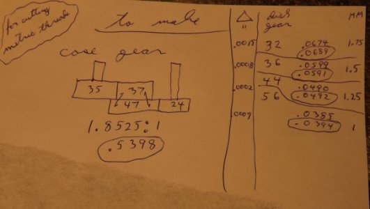
I'm planning to make 2 shafts that fit over the ones on lathe and are driven with the dogs. I will turn down the other end to fit gears that I have or will make. The shafts will pass through a steel plate for outboard support. These gears do not mesh but will have a compound (2 tier) (transposing) gear between them. The gear sizes I have calculated will give the 4 most popular metric thread pitches.

DSCF4052.JPG

DSCF4050.JPG

EDIT: The shafts are drive and driven.
 
I just realized I'll need one additional idler gear to get the proper output direction
 
Or I wonder if that could be done by reversing the feed???:D
 
It would seem that you can use the feed reverse, if it also reverses the lead screw, but I am not familiar with your lathe. Typically, using an idler is something that is used on milling machines to reverse spirals
 
Back
Top