show me DRO installs for an Atlas/Craftsman 101.07403 lathe

ARC-170

Jeff L.
H-M Lifetime Diamond Member
Joined
Oct 17, 2018
Messages
922
I'm considering mounting a DRO on my Atlas Craftsman 101.07403 lathe.

I've seen a few threads on adding DRO's to lathes, but I'm posting here because I want to know if anyone has added a DRO set-up to this particular lathe. I have some ideas, but don't want to re-invent the wheel.

I could mount the Z (spindle axis) DRO along the back and mount the bracket holding the read head to the carriage somehow.

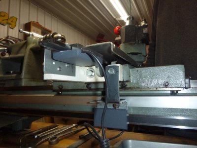
The cross-slide seems like the hardest place to add a DRO on these lathes because there are no flat/square surfaces that are big enough to easily mount anything. Here's a picture of the location I'm thinking I'd like to mount it, the right/tailstock side of the carriage.
lathe DRO 2.jpg

If anyone has any pictures, I'd love to see them. Thanks!
 
Don't know what DRO you are planning to use but the Igaging DRO's are commonly used on the Atlas/Craftsman lathes. Here is a video (not mine) that shows one way of mounting the DRO to the cross slide. This is basically how I mounted mine and it works well unless you want to use a taper attachment.

 
I'm considering mounting a DRO on my Atlas Craftsman 101.07403 lathe.

I've seen a few threads on adding DRO's to lathes, but I'm posting here because I want to know if anyone has added a DRO set-up to this particular lathe. I have some ideas, but don't want to re-invent the wheel.

If anyone has any pictures, I'd love to see them. Thanks!

Here are some photos of an Igaging DRO installation on my Atlas 10F. It's the 10" lathe, but very similar to your 12" 101.07403. I have had the DRO on the lathe for a couple of years and it has performed well. Bought it off Ebay for a very reasonable price. HTH, Bill

Edit: I just watched the video that 38Bill posted, and the the method of installing the scale for the X is very similar to the way I did it. (Maybe I pilfered his idea :oops:)
Here is the Installation on the X
DSC_0037.JPG

A view from the bottom of the X and the bracket for the Y
DSC_0031.JPG

A view from the rear showing the display
DSC_0035.JPG

And the front of the displayDSC_0034.JPG
 
Last edited:
I took some more pictures of my lathe so you can all see what I have to work with for mounting.
lathe tool rest 1 for DRO.jpg

lathe tool rest 2 for DRO.jpg

Not sure if I can mount the perpendicular to the long axis DRO inside the compound or not.

The long axis DRO seems easy enough to mount, but I might need to fabricate a bracket to hold both readers heads.

I'll try and sketch up some ideas later, but I still would like to know if anyone mounted a DRO on a lathe exactly like mine.
 
Not really many options for the Y axis. You either have to make a stand-off and mount it on the right side of the carriage or do something like the above video shows or like Bill's photos show. Here is mine. Its not pretty as I built it as a prototype using Delrin and scraps out of the junk bin but it works great so I never rebuilt it. Now that I have a mill I may actually make it pretty some day. Whatever you end up doing be sure that you have the means to allow the read head to be adjusted to the scale. My X scale is fastened to the lathe bed using the brackets that came with the DRO. The mounting holes are very easy to drill and tap. I also upgraded to the Absolute DRO with the larger readout and the ability to use a power adaptor instead of batteries. PS: I cut the Y scale to shorten it so it wasn't sticking out so far in back.
 

Attachments

  • P1020538.JPG
    P1020538.JPG
    888.3 KB · Views: 125
I've been meaning to get out to the shop and take some pictures for you, finally got around to it today. I used a low profile encoder, the full size is way too big. The encoder is mounted by drilling two holes in the top of the carriage and mounting it to an intermediate flat bar. The encoder pickup is attached to the crosslide via a 14 gauge sheet metal bracket bent at a 90 degree angle, it is attached to the crosslide via countersunk screws to allow for a low profile. A chip cover is made from 20 gauge sheet metal bent at 90 degrees and attached using the end cap mounting screws on top. I used a gingery brake to do the bending. So far it works pretty good. Good luck on your install.IMG_0022.jpgIMG_0023(Edited).jpgIMG_0024(Edited).jpg
 
Back
Top