show me DRO installs for an Atlas/Craftsman 101.07403 lathe

bill70j:
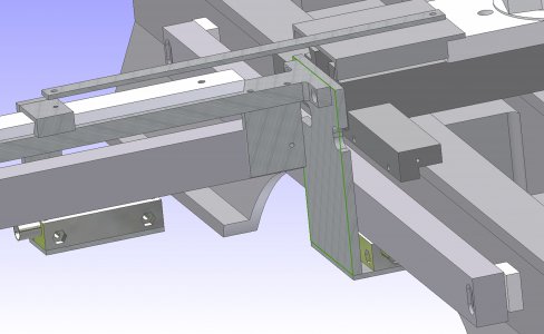
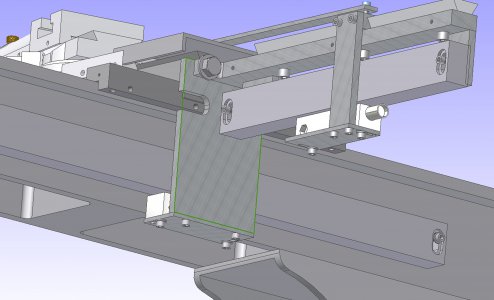
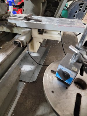
I'm planning on doing something similar on the long axis (X-axis, correct?). I see you mounted the aluminum block in such a way that it grips the screw heads holding the bearing plate. Any reason not to just screw the aluminum block onto the bearing plate using longer screws that replace the ones that hold the bearing plate? How well does your method hold the block on?
lathe long axis DRO holder idea 1.JPG

I want to use these screws to mount the block that holds the DRO. I thought I would just get longer ones. This plate just seems to hold the carriage on and not have any critical tolerances (or does it?):
lathe DRO block mounting location idea.jpg

The other option is to drill and tap holes in the bearing plate for separate screws. Thoughts?

CLARIFICATION
Just so I'm clear: is the X-axis is the long one (L-R as you are looking at the lathe/along the spindle axis) and the Y-axis is the short one (fore/aft; controls diameter of part)?

However, I thought the Z-axis was always the axis of rotation. In that case, using the right-hand rule-right hand, palm up, thumb to right, index away form you, middle finger straight up (so thumb is positive X, index is positive Y and middle is positive Z)-t if you orient your hand to point the middle finger along the axis of rotation, he long axis would be the Z-axis and the short one would be the Y-axis and there would be no X-axis.
 
Last edited:
Any reason not to just screw the aluminum block onto the bearing plate using longer screws that replace the ones that hold the bearing plate? How well does your method hold the block on?
Jeff:
I see no reason why your idea of longer bearing plate screws wouldn't work. The reason I didn't do it that way ---- is because I didn't think of it. The way I did it works just fine, but as I see it now - was far too exotic.

As you know, there are shims under those plates, but as long as you put them back the same way they came out you should be good , so no critical tolerances to worry about.

As far as drilling and tapping for additional screws, I have a personal bias against doing that - don't know why, I just do. On this installation, I did drill and tap for the two "long axis" scale brackets because I saw no way around it. I did however double-stick tape the aluminum swarf guard in place so saved drilling a couple of holes for that.

Good luck on your installation. We look forward to seeing your work in progress!

Bill
 
I'm considering mounting a DRO on my Atlas Craftsman 101.07403 lathe.

I've seen a few threads on adding DRO's to lathes, but I'm posting here because I want to know if anyone has added a DRO set-up to this particular lathe. I have some ideas, but don't want to re-invent the wheel.

I could mount the Z (spindle axis) DRO along the back and mount the bracket holding the read head to the carriage somehow.

The cross-slide seems like the hardest place to add a DRO on these lathes because there is no flat/square surfaces that are big enough to easily mount anything. Here's a picture of the location I'm thinking I'd like to mount it, the right/tailstock side of the carriage.
View attachment 305275

If anyone has any pictures, I'd love to see them. Thanks!
Here is my concept for mounting a full size glass scale to the Atlas for both Z and X Axes. I am in the process of machining mounting hardware and should have it working in a few days. Basically the X-Axis glass slide (15 CM travel) is mounted behind the carriage on a "T" shaped bar bolted to the rear of the carriage using the existing 3/8-16 tapped holes. A dovetail slide is included to ensure parallel travel. One concern I have is forcing the glass slide into an over-travel condition causing damage. As a result I am using a metal "push bar" with some type of shear pin or shear bolt that will snap before damage is done. I will likely include some physical stops on the dovetail slide to limit travel to safe amounts. The Z-axis is easier as shown in the images attached.
 

Attachments

  • Glass Scale mounting 2 on Atlas 10-36.jpg
    Glass Scale mounting 2 on Atlas 10-36.jpg
    1 MB · Views: 73
  • Glass Scale mounting 3 on Atlas 10-36.jpg
    Glass Scale mounting 3 on Atlas 10-36.jpg
    1.1 MB · Views: 68
  • Glass Scale mounting on Atlas 10-36.jpg
    Glass Scale mounting on Atlas 10-36.jpg
    962.9 KB · Views: 70
So here's what I did:

I made a block (at left) that holds the DRO rail to the compound slide. The block at right holds the reader.
DSC00021.JPG

Here it is with the cover on. I bent some sheet metal:
DSC00022.JPG

Here's a close-up of the attachment method. I used the existing screw at left and used a smaller diameter screw (at right) through the hole used for the original cover.
DSC00023.JPG

Here's a view of the long axis. I mounted the bracket to the slide using the existing screws. I needed to change one to a bolt because I can't get a screwdriver in there to tighten it. I have not attached the rail yet because I need to take the lathe apart to move it to another workbench. I wanted to show what I did in the meantime.
DSC00025.JPG

I took some measurements of the lathe then drew the needed views in AutoCAD. I knew that there would be some slop due to measuring errors and machining tolerances (I'm not that good!) so I made all the thru-holes a little big so I'd have some play to make adjustments.
 
I mounted Igauge dros on my 6" craftsman. I utilized the two 1/2" holes on the y axis for install. I printed some reader holders and a new lead screw cover. For the x axis I drilled 2 holes and threaded. Used the included mounts for that. I will upload pictures if I can figure out how to.
 

Attachments

  • IMG-20210804-WA0000.jpeg
    IMG-20210804-WA0000.jpeg
    1.8 MB · Views: 51
  • 16282850986308257662390436745517.jpg
    16282850986308257662390436745517.jpg
    1.4 MB · Views: 45
  • 16282851983594653023366144888526.jpg
    16282851983594653023366144888526.jpg
    1.2 MB · Views: 41
With those bars sticking out the back that many of you have used to hold the reader, you're halfway to having a taper attachment already.
 
Back
Top