- Joined
- Mar 16, 2016
- Messages
- 132
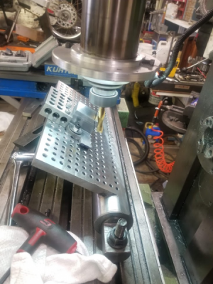
Fairly straight forward.
2 1/2 solid round bar stock, turned it to true. Bored 1 1/2" into both ends for the lugs.
Built the Lugs
here is one of them
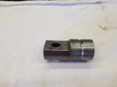
mounted it in the mill and cut a 1" deep slot in it.
Milled a flat piece of 3/4" steel plate and inserted it in the slot. Clamped it and welded to the bar. Once cooled I used my surface cutter and ran it down to height. so at zero degrees the table resting in a T slot on the mill table is exactly 2 high.
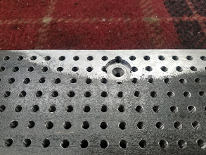
Drilled the field 1/2" on center grid using the grid feature on the DRO. 1/4x20
Flipped it upside down and bored it for my machinists jacks foot.
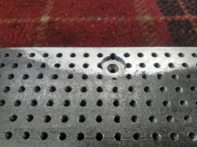
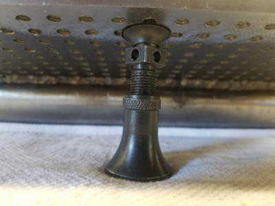
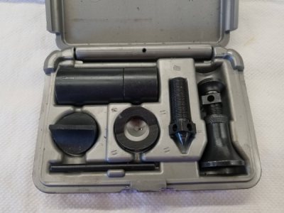
I use a Browne and Sharpe machinists jack I picked up on E-bay for 20 bucks
Last edited:


