

- Joined
- Jan 1, 2014
- Messages
- 233
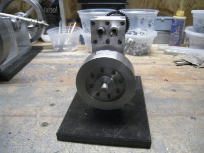
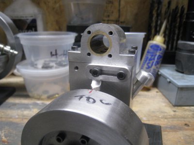
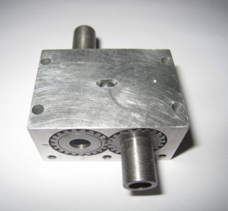
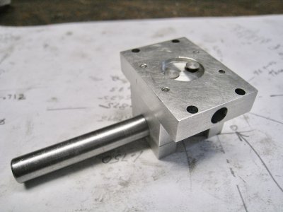
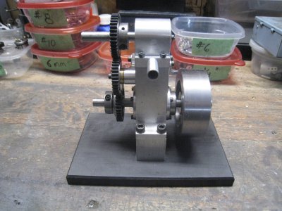
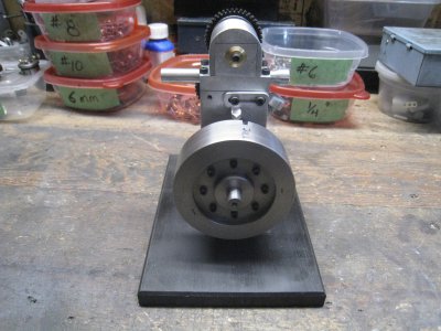
Wanted to try different valving ideas for a compressed air motor. The air V8 I made used a central rotary valve plus spring ball valves in the head. Wanted to try out rotary valves alone and maybe a OHV setup. Needed something simple to use as a platform so made a single cylinder lab motor.
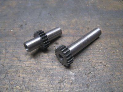
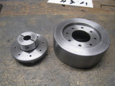
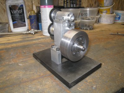
Because of space I won’t bore you with the motor details except that it is 5/8” bore and 1/2” stroke, wasn’t worried what it looked like. Used suitable RC car gears where needed.
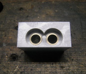
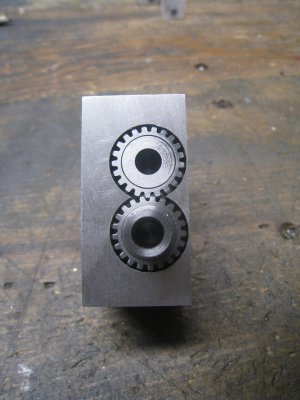
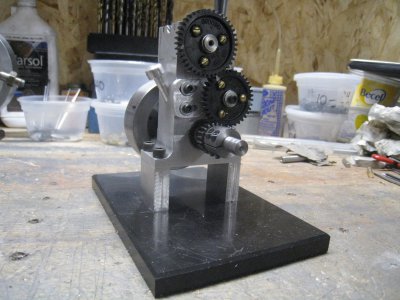
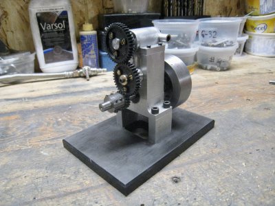
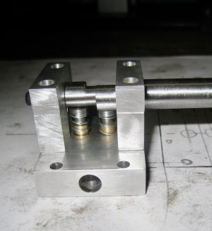
For the first setup I tried to make one rotary valve to do both the intake and exhaust functions but found it difficult so opted for dual valves. The timing was easy as they were geared 90 degrees apart and the ports into the head were drilled 90 degrees apart. The valves were 3/8” diameter so porting for the duration of 180 degrees of piston movement required .147” apertures. After putting all the parts together it worked and ran smooth, but not fast, maybe 1600 rpm. Maybe too much friction for a little piston and short stroke, heavy flywheel too, but success nevertheless.
Not being able to solve the single valve idea still bugged me, so gave it another go.
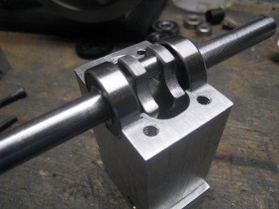
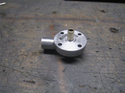
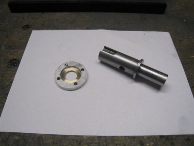
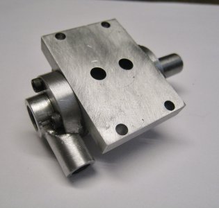
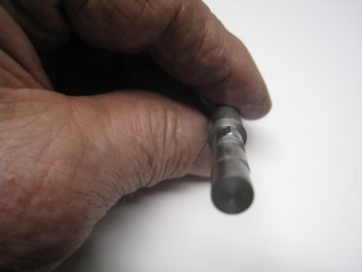
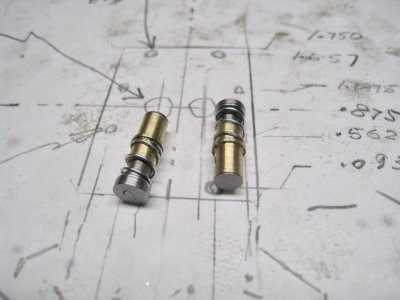
The original idea was to use a channel on the outside of the rotary valve to route the exhaust to a port sideways out of the head. The channel on the outside would have to accommodate the aperture opening through 90 degrees of valve travel (180 degrees of crank) and whatever extra continuing radial channel that was required to keep mated with an external port. Found there was no room to work with as the same thing was about to happen on the other side of the valve because of the next two cycle power stroke. So, rehashing the problem, it dawned on me that if the channels ran straight along the valve axis to the rear, then, an exhaust annulus machined into a rear cover would make it easy to stay mated with the rotating exhaust port. The annulus only needed to span 135 degrees. Also made the new valve .500” in diameter so uses .196” apertures. All the new pieces were made and the head was shaped as well to make it look better.This revised system ran much better and the motor runs at 3125 rpm, not a screamer, but satisfying none the less.
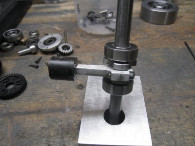
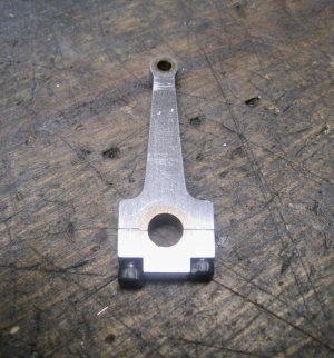
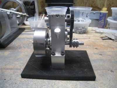
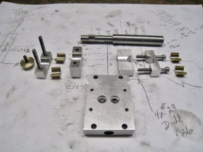
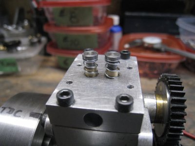
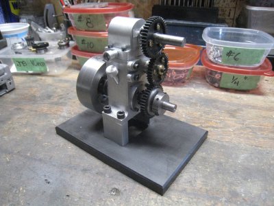
Now have just finished a OHV setup. Design was to keep it small and have the cam act directly on the valves. Made brass modules drilled to act as the valve guide and include the valve seat. The CRS valves have 5/32” stems, .200” head and 30 degree lip. Top of stem is drilled and tapped 4-40 with a custom flat topped screw to capture a .018” wire compression spring. The top of the screw also provides the flat surface for the cam to act on. The modules are .625” overall height. A side hole lines up with porting in the head to allow air in and exhaust out. These modules were then inserted in the head with loctite. The CRS cam was turned in the lathe and the lobes finished on the mill with the RT. Shape is what looked right to me and has .070” lift. Cam runs in brass bushings.
Was really surprised how nice the OHV setup worked. The open gearing is quiet at speed but noisy on slow down. The exhaust sounds great.
I chopped some video into short clips but can't get them to open after posting. Will ask the Moderator.
Because of space I won’t bore you with the motor details except that it is 5/8” bore and 1/2” stroke, wasn’t worried what it looked like. Used suitable RC car gears where needed.
For the first setup I tried to make one rotary valve to do both the intake and exhaust functions but found it difficult so opted for dual valves. The timing was easy as they were geared 90 degrees apart and the ports into the head were drilled 90 degrees apart. The valves were 3/8” diameter so porting for the duration of 180 degrees of piston movement required .147” apertures. After putting all the parts together it worked and ran smooth, but not fast, maybe 1600 rpm. Maybe too much friction for a little piston and short stroke, heavy flywheel too, but success nevertheless.
Not being able to solve the single valve idea still bugged me, so gave it another go.
The original idea was to use a channel on the outside of the rotary valve to route the exhaust to a port sideways out of the head. The channel on the outside would have to accommodate the aperture opening through 90 degrees of valve travel (180 degrees of crank) and whatever extra continuing radial channel that was required to keep mated with an external port. Found there was no room to work with as the same thing was about to happen on the other side of the valve because of the next two cycle power stroke. So, rehashing the problem, it dawned on me that if the channels ran straight along the valve axis to the rear, then, an exhaust annulus machined into a rear cover would make it easy to stay mated with the rotating exhaust port. The annulus only needed to span 135 degrees. Also made the new valve .500” in diameter so uses .196” apertures. All the new pieces were made and the head was shaped as well to make it look better.This revised system ran much better and the motor runs at 3125 rpm, not a screamer, but satisfying none the less.
Now have just finished a OHV setup. Design was to keep it small and have the cam act directly on the valves. Made brass modules drilled to act as the valve guide and include the valve seat. The CRS valves have 5/32” stems, .200” head and 30 degree lip. Top of stem is drilled and tapped 4-40 with a custom flat topped screw to capture a .018” wire compression spring. The top of the screw also provides the flat surface for the cam to act on. The modules are .625” overall height. A side hole lines up with porting in the head to allow air in and exhaust out. These modules were then inserted in the head with loctite. The CRS cam was turned in the lathe and the lobes finished on the mill with the RT. Shape is what looked right to me and has .070” lift. Cam runs in brass bushings.
Was really surprised how nice the OHV setup worked. The open gearing is quiet at speed but noisy on slow down. The exhaust sounds great.
I chopped some video into short clips but can't get them to open after posting. Will ask the Moderator.
Attachments
-
 IMG_8693.jpeg1.5 MB · Views: 19
 -
 IMG_8694.jpeg1.7 MB · Views: 19
 -
 IMG_8695.jpeg1.7 MB · Views: 18
 -
 IMG_8707.jpeg1.5 MB · Views: 18
 -
 IMG_8716.jpeg1.8 MB · Views: 17
 -
 IMG_8725.jpeg1.7 MB · Views: 17
 -
 IMG_8730.jpeg1.4 MB · Views: 18
 -
 IMG_8738.jpeg1.9 MB · Views: 19
 -
 IMG_8739.jpeg1.9 MB · Views: 19
 -
 IMG_8743.jpeg1.8 MB · Views: 18
 -
 IMG_8749.jpeg1.8 MB · Views: 17
 -
 IMG_8752.jpeg1.4 MB · Views: 16
 -
 IMG_8754.jpeg1.6 MB · Views: 15
 -
 IMG_8801.jpeg1.7 MB · Views: 17
 -
 IMG_8805.jpeg2.1 MB · Views: 17
 -
 IMG_9058.jpeg1.3 MB · Views: 17
 -
 IMG_9060.jpeg1 MB · Views: 17
 -
 IMG_9067.jpeg1.2 MB · Views: 17
 -
 IMG_9078.jpeg1.6 MB · Views: 17
 -
 IMG_9086.jpeg1.6 MB · Views: 17
 -
 IMG_9090.jpeg1.8 MB · Views: 17
 -
 IMG_9092.jpeg633.1 KB · Views: 17
 -
 IMG_9100.jpeg1.5 MB · Views: 22
 -
 IMG_9101.jpeg1.9 MB · Views: 23
 -
 IMG_9103.jpeg1.9 MB · Views: 22
 -
 IMG_9104.jpeg1.9 MB · Views: 20
Last edited:

