- Joined
- Jul 28, 2017
- Messages
- 2,366
11 years ago we moved into our new house. Like all houses, some things have started to fail. We already have had to replace our hot water heater, and recently some of the soft-close mechanisms in our kitchen drawers have failed. When pulling one of the affected drawers out to get something, initially the drawer behaves as usual -- it requires a noticeable bit of force to pull it out (this is to "arm" the retraction mechanism). But when it gets about one third of the way out it suddenly releases, along with a loud "sproing!" sound. At that point the drawer is very easy to pull the rest of the way out; but when closing it, there is _no_ soft-close action. If not careful, the drawer just bangs into the back of the cabinet. Rinse and repeat.
I pulled the drawer out and examined the mechanism to see if there was any way to repair or replace it. The soft-close is done with a spring-loaded piston and cylinder assembly, with a rod attached to the piston. There's a plastic piece on the end of the rod that either engages a pin on the side of the drawer or a pin on the fixed side of the drawer slide. Initially the latch is fixed to the drawer but when the drawer is pulled out it gets transferred to the drawer slide, releasing the drawer (the spring inside the cylinder is extended so the mechanism now is "cocked"). When the drawer is closed, the latch is transferred back to the drawer and the spring inside the cylinder pulls the drawer closed. The piston is used to keep it from flying back, using air pressure in the cylinder plus a slow leak to oppose the spring force.
The failure: that plastic piece on the end of the rod. The plastic either breaks or wears down to the point where it doesn't latch. Looking at replacements, I saw exactly the same design so I knew they would fail after awhile, too. So I decided to make my own soft-close gizmo.
My design goal was to come up with something that either wouldn't wear out, or, if it did, could be easily repaired. To satisfy the former requirement I looked at approaches that were as simple as possible, and decided that the problem should be broken down into two separate parts: a pneumatic damper that would slow the drawer down as it closed, and a long-range magnetic "puller" that could automatically retract the drawer. I first built and installed the damper because it was easiest to make, and have done a lot of theoretical work to design the long-range magnetic puller. That part has been interesting because I've been using an electromagnetic modelling program based on finite element analysis. I'll show some results of that at the end of this long post.


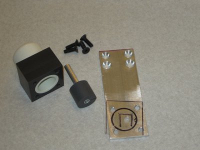
The top photo shows just the pneumatic damper. The piston and cylinder are made from ABS. The cap is an ordinary plumbing end-cap, drilled so the piston rod can pass through it. The black square block(s) are drilled/tapped, and attached to the aluminum base. I made a simple flap type valve that installs over a hole in the aluminum base, so when it's all assembled the rod/piston is easily pulled out but develops significant back-force when pushed in because the flap valve closes. Air leakage around the piston/cylinder wall allows it to slowly close. The flap valve was cut from .005" thick mylar, then the flap was cut with a razor blade.
The piston rod has a small magnet glued inside the end. It "sticks" to a 1" x 1" x 1/8"-thick steel plate that is attached to the back of the drawer. The idea is that the magnet has strong enough attraction to pull the piston all the way out to the cylinder end-cap, but then release as the drawer is pulled further out. The piston rod is fully extended so when the drawer is pushed back in, the damper rod acts to slow the drawer down.
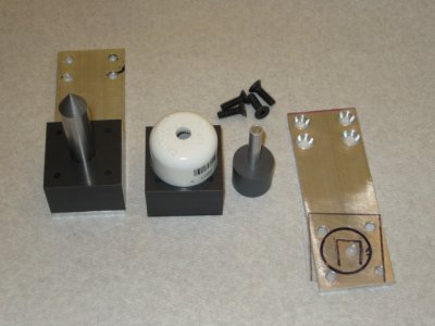
The bottom photo shows the parts in a different perspective, plus an alignment tool I made to make sure that the steel plate on the back of the drawer would be in the right place for the damper magnet. The aluminum plate and PVC base are exactly the same dimensions. I turned a steel rod down to a point so it would mark the back of the drawer where the steel plate needs to be installed. I plan on making my magnetic "closer" mechanism to the same overall dimensions so I can use my alignment fixture for that, too.
While this damper design doesn't completely eliminate the possibility of wearout, I believe it is much more robust than the original mechanism. And it will be easy enough to repair if it does develop wear.
So, on to the long-range "puller". A simple magnetic latch, basically a flat steel plate and a magnet, can have very high holding force. That's not the problem. The difficulty is that the force between the magnet and steel plate falls off very rapidly with distance. I was thinking of something like a solenoid, which can exert significant force over the extent of its stroke -- but it had to use a permanent magnet instead of a coil of wire and electrical current. Figuring out the right geometry looked like it could involve a lot of time-consuming (and material-consuming) experiments, so I looked around for some kind of magnetic-field computer modelling program and found FEMM, a program that solves electrostatic and magnetic problems. It's possible to use it to determine the force acting between arbitrarily-shaped magnets and steel pieces. It also can be set up using a scripting language so it was relatively easy to vary dimensions and see how the behavior of the system changed as a result.
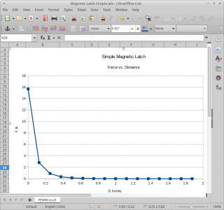
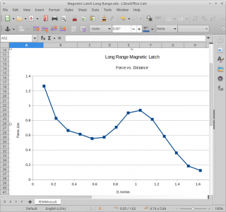
Long story short, I found that a straight steel tube and cylindrical magnet didn't work very well -- once the magnet fully entered the cylinder, it no longer exerted any axial force. However, a tube with a tapered interior was a different story. Below you can see the results of two simulations -- one is for a typical flat magnet and steel plate, pretty much your standard magnetic latch; and another that models a tapered tube and cylindrical magnet:


The force vs. distance plot shows that my tapered cylinder isn't very linear but it doesn't have to be in order to do what I want it to. The cool thing is that it starts to exert significant force almost two inches away. And since it's based on magnetism, it shouldn't wear out any time soon. If ever.
I have the material(s) to build one of these but haven't had the time to do the machining work. Summertime activities put a halt to machining stuff, but, now that it's early November, I've got more time to play around with things like this. I'd love to get my hands on a load cell so I can compare simulated to actual results but that's only going to happen if I get really poor results from the prototype.
More later. Living up to my handle on this one, for sure
I pulled the drawer out and examined the mechanism to see if there was any way to repair or replace it. The soft-close is done with a spring-loaded piston and cylinder assembly, with a rod attached to the piston. There's a plastic piece on the end of the rod that either engages a pin on the side of the drawer or a pin on the fixed side of the drawer slide. Initially the latch is fixed to the drawer but when the drawer is pulled out it gets transferred to the drawer slide, releasing the drawer (the spring inside the cylinder is extended so the mechanism now is "cocked"). When the drawer is closed, the latch is transferred back to the drawer and the spring inside the cylinder pulls the drawer closed. The piston is used to keep it from flying back, using air pressure in the cylinder plus a slow leak to oppose the spring force.
The failure: that plastic piece on the end of the rod. The plastic either breaks or wears down to the point where it doesn't latch. Looking at replacements, I saw exactly the same design so I knew they would fail after awhile, too. So I decided to make my own soft-close gizmo.
My design goal was to come up with something that either wouldn't wear out, or, if it did, could be easily repaired. To satisfy the former requirement I looked at approaches that were as simple as possible, and decided that the problem should be broken down into two separate parts: a pneumatic damper that would slow the drawer down as it closed, and a long-range magnetic "puller" that could automatically retract the drawer. I first built and installed the damper because it was easiest to make, and have done a lot of theoretical work to design the long-range magnetic puller. That part has been interesting because I've been using an electromagnetic modelling program based on finite element analysis. I'll show some results of that at the end of this long post.


The top photo shows just the pneumatic damper. The piston and cylinder are made from ABS. The cap is an ordinary plumbing end-cap, drilled so the piston rod can pass through it. The black square block(s) are drilled/tapped, and attached to the aluminum base. I made a simple flap type valve that installs over a hole in the aluminum base, so when it's all assembled the rod/piston is easily pulled out but develops significant back-force when pushed in because the flap valve closes. Air leakage around the piston/cylinder wall allows it to slowly close. The flap valve was cut from .005" thick mylar, then the flap was cut with a razor blade.
The piston rod has a small magnet glued inside the end. It "sticks" to a 1" x 1" x 1/8"-thick steel plate that is attached to the back of the drawer. The idea is that the magnet has strong enough attraction to pull the piston all the way out to the cylinder end-cap, but then release as the drawer is pulled further out. The piston rod is fully extended so when the drawer is pushed back in, the damper rod acts to slow the drawer down.
The bottom photo shows the parts in a different perspective, plus an alignment tool I made to make sure that the steel plate on the back of the drawer would be in the right place for the damper magnet. The aluminum plate and PVC base are exactly the same dimensions. I turned a steel rod down to a point so it would mark the back of the drawer where the steel plate needs to be installed. I plan on making my magnetic "closer" mechanism to the same overall dimensions so I can use my alignment fixture for that, too.
While this damper design doesn't completely eliminate the possibility of wearout, I believe it is much more robust than the original mechanism. And it will be easy enough to repair if it does develop wear.
So, on to the long-range "puller". A simple magnetic latch, basically a flat steel plate and a magnet, can have very high holding force. That's not the problem. The difficulty is that the force between the magnet and steel plate falls off very rapidly with distance. I was thinking of something like a solenoid, which can exert significant force over the extent of its stroke -- but it had to use a permanent magnet instead of a coil of wire and electrical current. Figuring out the right geometry looked like it could involve a lot of time-consuming (and material-consuming) experiments, so I looked around for some kind of magnetic-field computer modelling program and found FEMM, a program that solves electrostatic and magnetic problems. It's possible to use it to determine the force acting between arbitrarily-shaped magnets and steel pieces. It also can be set up using a scripting language so it was relatively easy to vary dimensions and see how the behavior of the system changed as a result.
Long story short, I found that a straight steel tube and cylindrical magnet didn't work very well -- once the magnet fully entered the cylinder, it no longer exerted any axial force. However, a tube with a tapered interior was a different story. Below you can see the results of two simulations -- one is for a typical flat magnet and steel plate, pretty much your standard magnetic latch; and another that models a tapered tube and cylindrical magnet:


The force vs. distance plot shows that my tapered cylinder isn't very linear but it doesn't have to be in order to do what I want it to. The cool thing is that it starts to exert significant force almost two inches away. And since it's based on magnetism, it shouldn't wear out any time soon. If ever.
I have the material(s) to build one of these but haven't had the time to do the machining work. Summertime activities put a halt to machining stuff, but, now that it's early November, I've got more time to play around with things like this. I'd love to get my hands on a load cell so I can compare simulated to actual results but that's only going to happen if I get really poor results from the prototype.
More later. Living up to my handle on this one, for sure


 ). somethings got to give.