

-
Welcome back Guest! Did you know you can mentor other members here at H-M? If not, please check out our Relaunch of Hobby Machinist Mentoring Program!
You are using an out of date browser. It may not display this or other websites correctly.
You should upgrade or use an alternative browser.
You should upgrade or use an alternative browser.
Some work on a TX650.
- Thread starter th62
- Start date
- Joined
- Aug 6, 2015
- Messages
- 3,861
Totally agree!Lacing is easy, tensioning is a black art!
Lacing is super easy, probably the simplest job you can do on a bike. Likewise for tensioning. Once you have trued the rim both side to side and eccentrically you just need to tap the spokes, then tighten or loosen the nipples so you get the same tone. You'll never get them exactly the same, duen to some spokes touching and some not. Trueness of the rim and so on. How tight, now that's the art: Tight enough so they don't work their way loose, but not tight enough so the spokes will snap. There are such things as spoke torque wrenches, but good luck getting them all the same and the rim trued as well. About all the tension wrenches are good for is assisting in getting roughly the right ring from the spokes
when tapped. But take heart, not even manufacturers can get that right all the time. I've had spokes on new wheels on new bikes come loose or snap. Practice and experience, attention to what you are doing, not rushing and having pride in your work are key. Unfortunately, some of those things go out the window at commercial shops.
when tapped. But take heart, not even manufacturers can get that right all the time. I've had spokes on new wheels on new bikes come loose or snap. Practice and experience, attention to what you are doing, not rushing and having pride in your work are key. Unfortunately, some of those things go out the window at commercial shops.
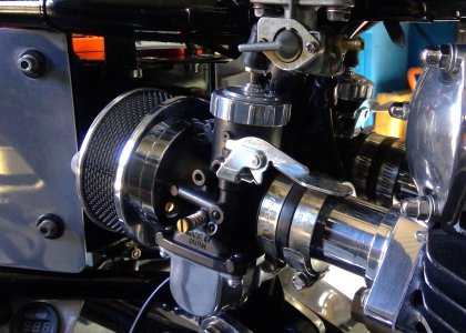
Well, I finally got around to finishing off the right side filter, and damn it looks good. It gives a nice unobstructed air flows, much better than pods. My plan on heating and cooling didn't work too well, much to hard to handle all the bits and pieces and tooling trying to press them together, so, I ended up pressing together cold.
Same with the sizing, .020mm press fit was much too much, so after a few tries I got a good fit by decreasing it to about .04mm. And of course my day wouldn't be complete without misplacing parts, I lost the idle mixture screw spring, no idea where I'm going to get one of them from.
All I have to do now is make an identical one for the left carb from that great slab of aluminium I spent yesterday tracking down, and beat up a rear plate. But first I'll make another fuel distributor block to keep the hosing neat and simple.
If I can remember, I'll take lots of pics of the machining and fabrication process and bore you all to tears with them.
Attachments
-
 WIN_20221221_14_59_56_Pro.jpg326.8 KB · Views: 13
 -
 WIN_20221221_14_38_07_Pro.jpg463.3 KB · Views: 9
 -
 WIN_20221221_14_38_19_Pro.jpg215 KB · Views: 9
 -
 WIN_20221221_14_50_34_Pro.jpg588.2 KB · Views: 10
 -
 WIN_20221221_14_54_43_Pro.jpg454.4 KB · Views: 11
 -
 WIN_20221221_14_55_01_Pro.jpg364.6 KB · Views: 11
 -
 WIN_20221221_14_56_05_Pro.jpg585.7 KB · Views: 12
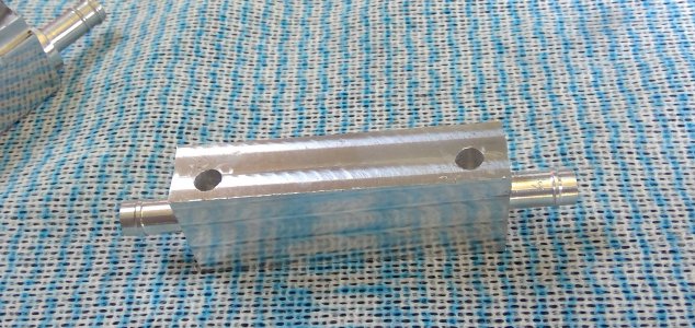
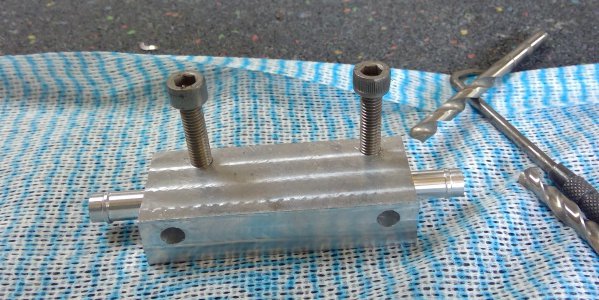
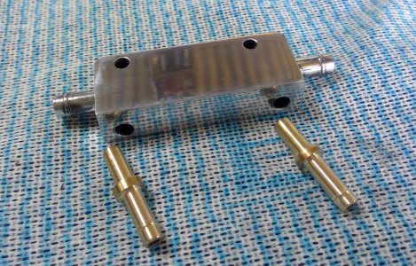
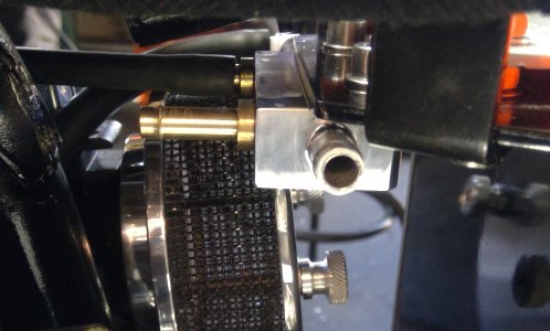
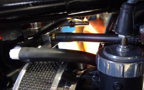
I did warn you: Here's loads of pictures taken while making a new fuel distributor block. It's little smaller than the first one I made and routes the hoses from petcock to carb nice and neatly, it also levels the fuel on both sides of the tank so one carb doesn't run dry when the fuel level gets low.
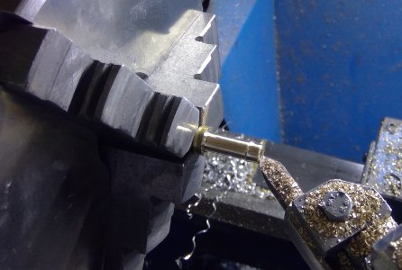
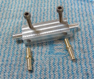
The block is drilled through left to right 5.5mm and has barbs machined on the end to take the 8mm hose going to the carbs. Two 6mm brass barbs are pressed in place on the front which take the hoses from the petcock via a couple of inline filters.
The block is drilled through left to right 5.5mm and has barbs machined on the end to take the 8mm hose going to the carbs. Two 6mm brass barbs are pressed in place on the front which take the hoses from the petcock via a couple of inline filters.
Attachments
-
 1.jpg260 KB · Views: 7
 -
 2.jpg449.3 KB · Views: 6
 -
 3.jpg529.7 KB · Views: 5
 -
 4.jpg798.2 KB · Views: 5
 -
 5.jpg535.9 KB · Views: 5
 -
 6.jpg784.5 KB · Views: 5
 -
 7.jpg677.8 KB · Views: 5
 -
 8.jpg481.8 KB · Views: 5
 -
 9.jpg454.7 KB · Views: 4
 -
 11.jpg813 KB · Views: 5
 -
 12_.jpg843.2 KB · Views: 5
 -
 13.jpg525.4 KB · Views: 5
 -
 '14.jpg799.4 KB · Views: 7
 -
 15.jpg832.6 KB · Views: 7
 -
 16.jpg374.7 KB · Views: 8
 -
 18.jpg335.9 KB · Views: 7
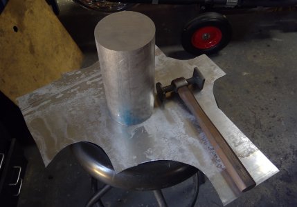
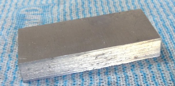
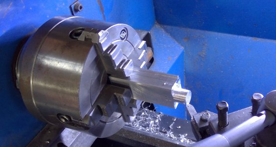
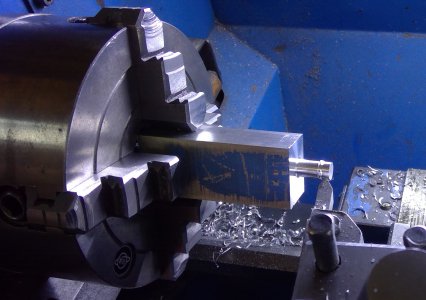
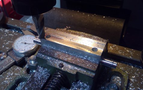
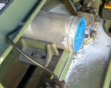
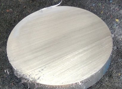
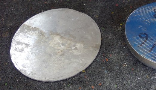
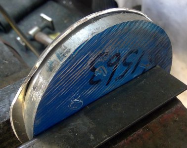
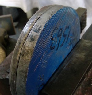
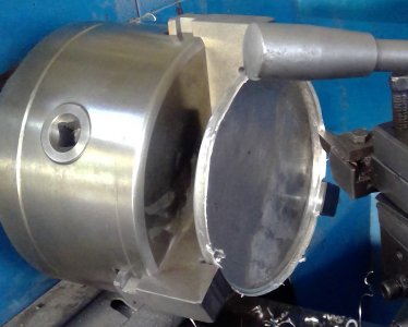
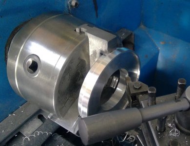
Here’s the process used making the air filters. I took sizes of the first filter I made and replicated them to the second. This time I took lots of pictures to outline the steps in making them. I cut a 15mm slice off the 101.6mm lump of ally and turned down one end to 97.4mm, then cut a piece of 1.7mm sheet to around 111-mm in diameter, stuck them together and bashed the overhang until there wasn’t one. I have to use my left hand now, as the right elbow complains. Sound easy, but it’s not, out of every 10 strikes, I think I miss about nine.
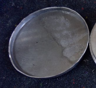
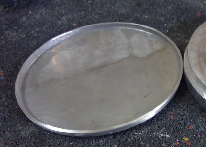
Once formed, I mounted it in the four jaw, and turned the overhang down to 3mm, then smoothed out all the scratches and what not with sand paper, finishing off with the random orbital sander with 240 grit.
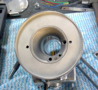
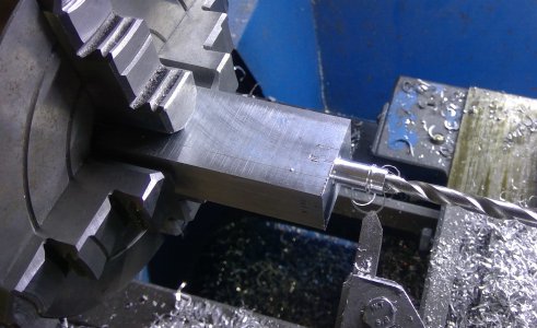
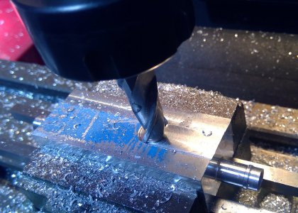
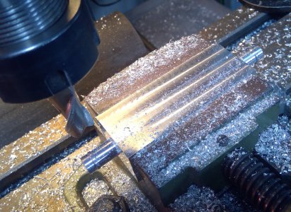
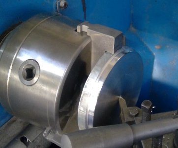
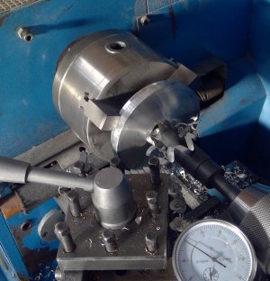
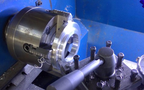
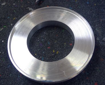
Next, I mounted the 15mm slab in the three jaw using the turned down area and drilled through with a 25mm bit, machined the outer diameter to 101.4mm, machined out the centre leaving a 2mm wide lip on the periphery, 3mm deep, then bored out the 25mm centre hole to 57.3mm to fit the 57.4 mm carb bell mouth. .10 mm proved a little tight, .07 would have been better I think.
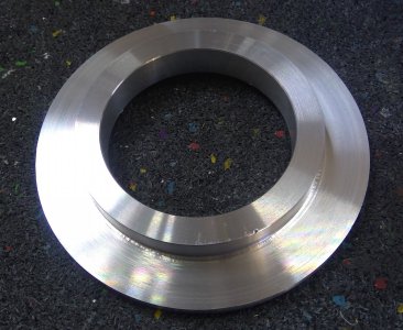
I flipped the slab over and mounted it in the four jaw, then spent a couple of hours trying to centre the damn thing, then turned down the inner mounting ring so its 8mm wide and the flat body of the filter 2mm thick. Final step, turn down the inner mounting ring so its 9.8mm deep.
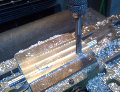
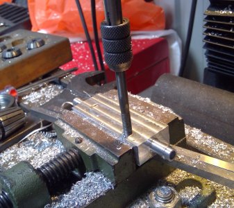
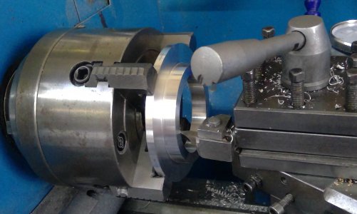
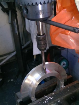
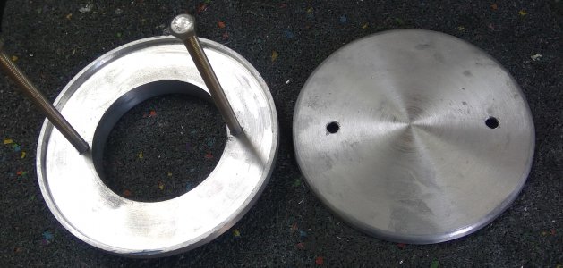
The cutting tool was then centred., spot on, and used to scribe a line across the back of the centre mounting ring. After removing from the chuck I found the centre point using a calliper, centre popped it, mounted it on the mill and drilled the centre pops with a 4mm bit, then mounted it on the pedestal drill, centred the holes and tapped the 4mm holes with a 5mm x .8 tap. The plate was then turned on its side, and drilled and tapped in the centre of the centre ring at 90degrees to the other two holes on the face.
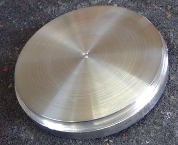
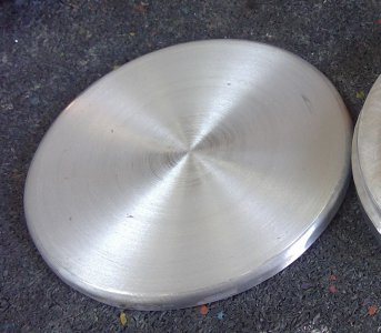
The piece was mounted in the three jaw again and using 240 grit any cutting ridges were smoothed over, then both plates were polished.
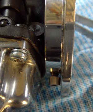
The knurled securing nuts were turned up from a piece of 20mm stock, tapped 5mm and then knurled using the scissor knurler. These were mostly done by eye, so won’t be absolutely identical. You’d need a calliper to pick up the difference though, so good are my four eyes.
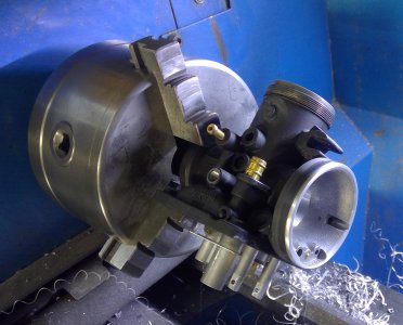
The carb body was mounted in the three jaw and a file used to remove the ridge at the beginning of the bell mouth. The face of the bell mouth was pretty rough, so I took the time to smooth that with some emery. The turned piece was located over the bell mouth, the assembly was then stuck in the vice and pressed into place.
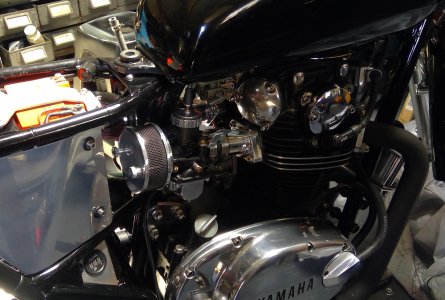
The lead into the bell mouth is flat, so not a perfect shape for induction. You can recess the filter lower on the bell mouth, creating a bit of a lip on the outer periphery of the bell mouth to improve induction, but realistically the improvement in induction wouldn’t be worth the time.
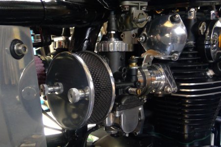
Both filters fit well and the hoses from the fuel distributor block lead over the filters nice and neatly. Happy with the outcome, except the inner knurled nuts are a little difficult to get to, probably due more to the fact my fingers are fused, but I can turn them with a little bit of messing around, better still, use the wife, her fingers aren’t fused. I’ve yet to get some perforated sheet metal to replace the stainless crap I used to keep the foam in place.
Once formed, I mounted it in the four jaw, and turned the overhang down to 3mm, then smoothed out all the scratches and what not with sand paper, finishing off with the random orbital sander with 240 grit.
Next, I mounted the 15mm slab in the three jaw using the turned down area and drilled through with a 25mm bit, machined the outer diameter to 101.4mm, machined out the centre leaving a 2mm wide lip on the periphery, 3mm deep, then bored out the 25mm centre hole to 57.3mm to fit the 57.4 mm carb bell mouth. .10 mm proved a little tight, .07 would have been better I think.
I flipped the slab over and mounted it in the four jaw, then spent a couple of hours trying to centre the damn thing, then turned down the inner mounting ring so its 8mm wide and the flat body of the filter 2mm thick. Final step, turn down the inner mounting ring so its 9.8mm deep.
The cutting tool was then centred., spot on, and used to scribe a line across the back of the centre mounting ring. After removing from the chuck I found the centre point using a calliper, centre popped it, mounted it on the mill and drilled the centre pops with a 4mm bit, then mounted it on the pedestal drill, centred the holes and tapped the 4mm holes with a 5mm x .8 tap. The plate was then turned on its side, and drilled and tapped in the centre of the centre ring at 90degrees to the other two holes on the face.
The piece was mounted in the three jaw again and using 240 grit any cutting ridges were smoothed over, then both plates were polished.
The knurled securing nuts were turned up from a piece of 20mm stock, tapped 5mm and then knurled using the scissor knurler. These were mostly done by eye, so won’t be absolutely identical. You’d need a calliper to pick up the difference though, so good are my four eyes.
The carb body was mounted in the three jaw and a file used to remove the ridge at the beginning of the bell mouth. The face of the bell mouth was pretty rough, so I took the time to smooth that with some emery. The turned piece was located over the bell mouth, the assembly was then stuck in the vice and pressed into place.
The lead into the bell mouth is flat, so not a perfect shape for induction. You can recess the filter lower on the bell mouth, creating a bit of a lip on the outer periphery of the bell mouth to improve induction, but realistically the improvement in induction wouldn’t be worth the time.
Both filters fit well and the hoses from the fuel distributor block lead over the filters nice and neatly. Happy with the outcome, except the inner knurled nuts are a little difficult to get to, probably due more to the fact my fingers are fused, but I can turn them with a little bit of messing around, better still, use the wife, her fingers aren’t fused. I’ve yet to get some perforated sheet metal to replace the stainless crap I used to keep the foam in place.
Attachments
-
 1.jpg516.3 KB · Views: 6
 -
 2.jpg203.2 KB · Views: 4
 -
 3.jpg219.5 KB · Views: 3
 -
 4.jpg376.3 KB · Views: 3
 -
 5.jpg616.4 KB · Views: 3
 -
 6.jpg500.2 KB · Views: 3
 -
 7.jpg261.2 KB · Views: 3
 -
 8.jpg416.2 KB · Views: 3
 -
 9.jpg181.9 KB · Views: 3
 -
 10.jpg339.9 KB · Views: 3
 -
 11.jpg375.4 KB · Views: 3
 -
 12.jpg322.7 KB · Views: 3
 -
 13.jpg473.8 KB · Views: 3
 -
 14.jpg533.9 KB · Views: 4
 -
 15.jpg613.3 KB · Views: 4
 -
 16.jpg370.1 KB · Views: 4
 -
 17.jpg489 KB · Views: 4
 -
 18.jpg440.2 KB · Views: 4
 -
 19.jpg156.7 KB · Views: 6
 -
 20.jpg682.3 KB · Views: 7