Now the bike is almost finished, just needs the seat covered and tyres, so I put on my glasses and cast a critical eye over it. Story of my life – never, ever happy, and what do you know, I found a few things I’m not happy with, so, I can start making parts for it again, whoo hoo!. First up was a new spin on filter/cooler. The current one totally underwhelms me: hoses look untidy, the spin on filter mount looks too blocky, so, that went in the bin. One of the screws holding the mount to the engine bracket was a bit hard to get at, so, the right engine mount went in the bin. The cooler bracket is just plain terrible, didn’t like the mounting method nor the look of it, plus the rubbers I felt were too small, so that also went in the bin, along with the left engine mount.
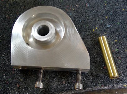
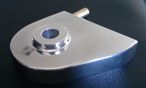
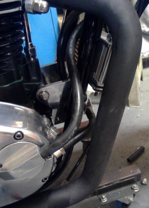
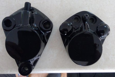
So, back to work: first up was a new spin on filter mount, I put a little shape into this one: rounded the edges, turned a cone on top and pressed the inlet spigot into the side of the mount, so the outlet hose from the front of right engine cover is only around 4’long and attaches to the inlet spigot of the spin on mount on the side, just in front of the engine mount. Much more neaterer!
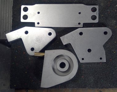
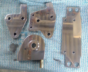
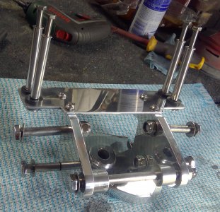
Next came some new engine brackets. The spin on mount is still mounted in the same manner, just set further back, so, the engine bracket protrudes further back, almost touching the engine case. This allows the rear allen head that was hiding behind the down tube to be moved further back, so now it is to thebrearnof the downtube and thus easy to get at.
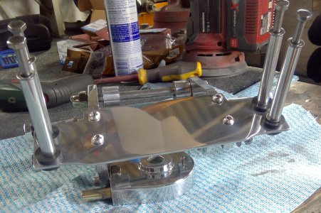
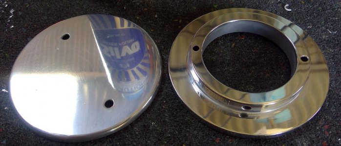
Next came the cooler mount, the original I made was a piece of 3mm ally, bent at a right angle and bolted to the front of the engine brackets via four allen heads. Didn’t like that, so I extended a goose neck on the front of the engine brackets out about 30mm and drilled and tapped holes in top for mounting the cooler bracket.
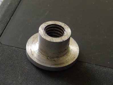
The cooler bracket, is now just a flat section of 3mm ally, with larger holes drilled to take bigger, thicker gromets and is secured to the top of the engine mount goose neck protrusions via four stainless button heads. To mount the cooler to the bracket I spun up four threaded T nuts that are inserted into the gromets from underneath and the four long bolts secure the cooler to the top of the bracket. The T nuts prevent the gromets from being squished too much.
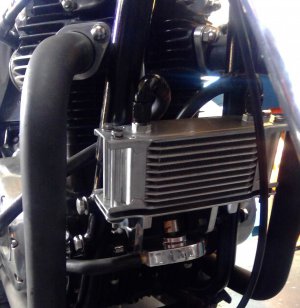
Now I just have the one long hose over the engine bracket connecting the cooler outlet spigot to the right engine cover. A hose connects the spin on mount spigot on top to the inlet on the cooler. I’ll retain the black rubber hoses as I don’t like the look of braided hose: to silvery and hard to keep clean down there with all the road debris and the black hose is a little less intrusive.


 21.jpg430.2 KB · Views: 11
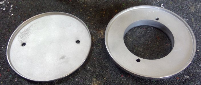 22.jpg402.5 KB · Views: 9
 23.jpg351.2 KB · Views: 8
 24.jpg310.3 KB · Views: 10
 25.jpg415.1 KB · Views: 9
 26.jpg377.7 KB · Views: 9
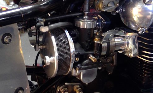 27.jpg357.5 KB · Views: 9
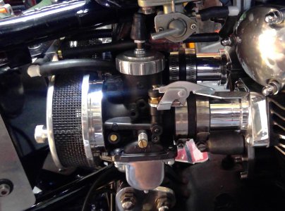 28.jpg485.1 KB · Views: 9
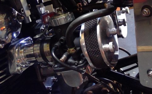 29.jpg357.9 KB · Views: 8
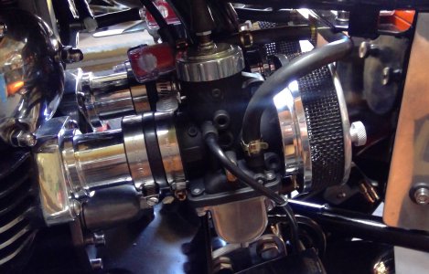 30.jpg492.4 KB · Views: 8
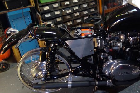 31.jpg613.7 KB · Views: 8
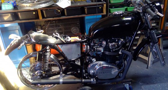 32.jpg523.8 KB · Views: 12