Some work on a TX650.

I was going to plumb the read valve engine breather into the pancake filters, but didn't like the idea of breathing sump gasses into the inlet, so, I made this catch can.

Not quite finished yet, I rushed it toward the end to see what it'd look like, happy with the result, So I'll probably build a neater one, with a few changes of course.

Matches the pancake filters, but almost unnoticeable
 

Attachments

  • WIN_20230311_13_51_21_Pro.jpg
    WIN_20230311_13_51_21_Pro.jpg
    523.4 KB · Views: 12
  • WIN_20230311_14_40_07_Pro.jpg
    WIN_20230311_14_40_07_Pro.jpg
    405.6 KB · Views: 12
  • WIN_20230312_15_26_10_Pro.jpg
    WIN_20230312_15_26_10_Pro.jpg
    204.4 KB · Views: 11
  • WIN_20230312_15_37_07_Pro.jpg
    WIN_20230312_15_37_07_Pro.jpg
    466.6 KB · Views: 10
  • WIN_20230312_15_38_24_Pro.jpg
    WIN_20230312_15_38_24_Pro.jpg
    444.6 KB · Views: 10
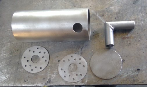
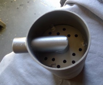
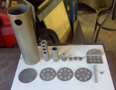
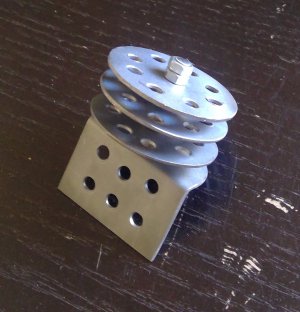
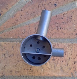
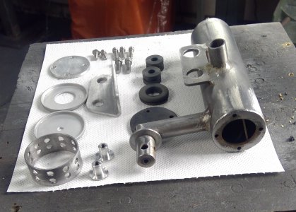
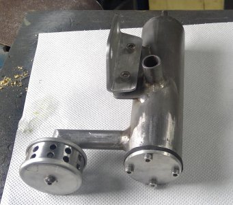
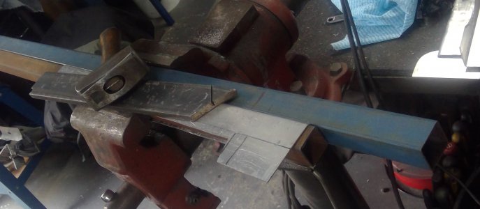
So, I finally settled on a catch can design and built it. The first one was simply too big, creating mounting problems, so that was binned. The final one is made of 42mm tube with four baffles. Instead of welding the baffles inside of the tube, I fixed them together with a 4mm screwed and peened the end so it wouldn’t come apart, the baffle cartridge was then pressed into place resting on top of the intake tube so it won’t float around. The intake tube stretches across the diameter of the 42mm tube and has three exit holes underneath. For the blowby gas to escape it has to exit via the four baffles and finally through some stainless mesh before exiting through the air filter on top, set between the two carb filters.

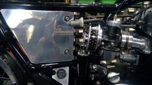
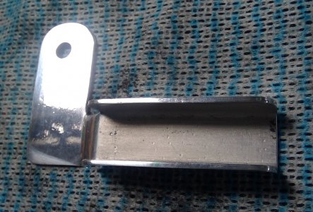
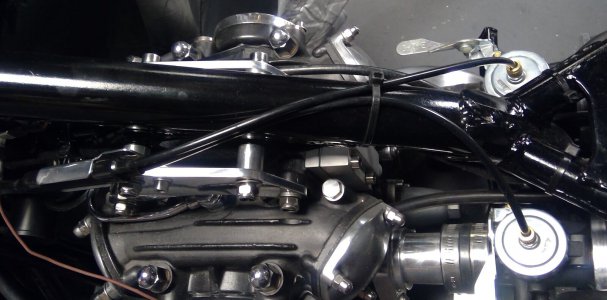
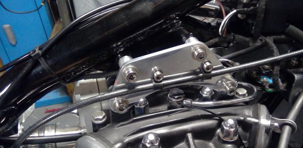
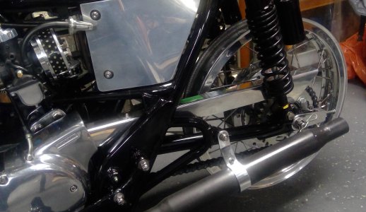
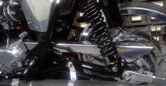
I’ve gone with a remote empty point via a tap connected to the catch can by a rubber hose. The filtering medium inside the can is replaceable via the top plate secured on top by four 4mm stainless allens. The can is mounted to an aluminium bracket by two rubber gromets and two threaded T nuts to stop the gromet from being squished too far, then fixed to the right, rear engine bracket.

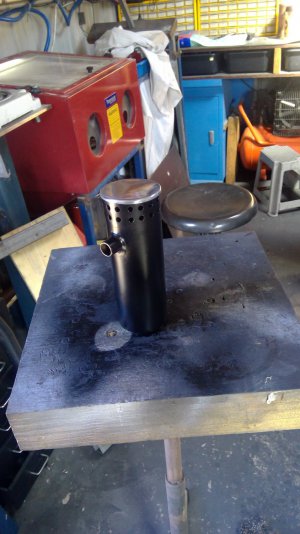
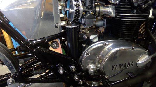
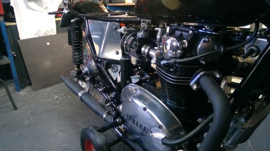
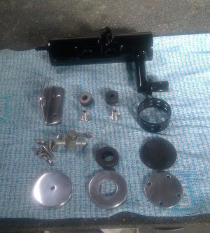
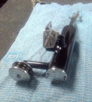
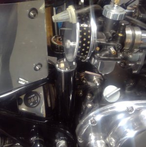
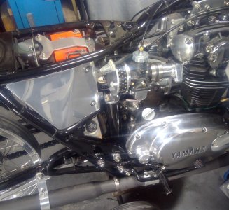
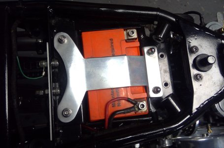
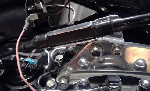
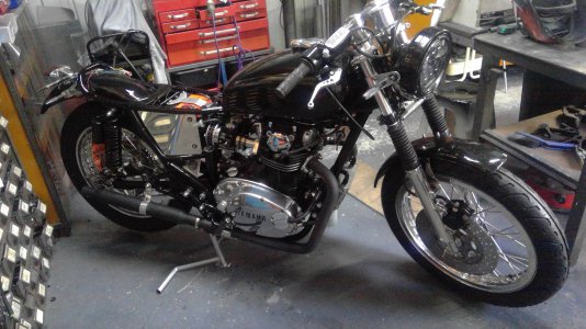
Mounting the can proved a little troublesome: behind the motor over top of the swing arm pivot is the only place I could find to mount it. To make it less noticeable I painted it black and welded an outlet on the side so I could mount the final filter between the two carb filters. It is only a small catch can with around 220ml capacity, that’s in total of course, realistically only around 100mm under the baffles. If it proves too small, I can fit a larger container under the swingarm connected to the catch can outlet by a rubber hose.

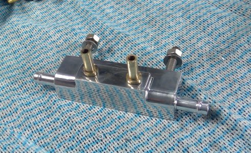
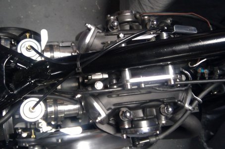
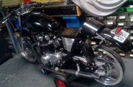
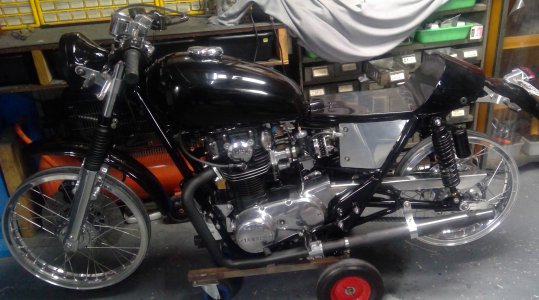
It’s very busy in this are area now, two carbs, three filters, catch can, fuel distributor block, making it a little difficult to remove the air filter caps.
 

Attachments

  • 1.jpg
    1.jpg
    424.8 KB · Views: 10
  • 2.jpg
    2.jpg
    270.4 KB · Views: 7
  • 4.jpg
    4.jpg
    353.3 KB · Views: 5
  • 5.jpg
    5.jpg
    561.4 KB · Views: 6
  • 6.jpg
    6.jpg
    498.8 KB · Views: 5
  • WIN_20230324_10_06_19_Pro.jpg
    WIN_20230324_10_06_19_Pro.jpg
    440.7 KB · Views: 5
  • WIN_20230324_11_12_24_Pro.jpg
    WIN_20230324_11_12_24_Pro.jpg
    383.7 KB · Views: 4
  • WIN_20230324_12_04_01_Pro.jpg
    WIN_20230324_12_04_01_Pro.jpg
    234.8 KB · Views: 7
  • WIN_20230324_12_04_51_Pro.jpg
    WIN_20230324_12_04_51_Pro.jpg
    366.1 KB · Views: 9
125k miles on my GL1800, and never had a drop of moisture in the drain. Never had any in the catch bottle on my GL1000, either. Still, so much better than the old "road draft" from the 50's. I remember the big grease streak in the center of each lane from that. Bikes had to avoid at all cost! Even in the '70s, I was very careful to stay in the tire tracks at every light in Charleston, SC and realize that footing in the center would be iffy.
 
Here it is, another fuel distributor block - number four. Just couldn't help myself.

I moved the inlet spigots closer together, milled a step at the front, round off the edge either side and mounted the block in the battery clamp holes, so it sits further back than it used to, thus giving more room to get at the air filters.

But, the old mounting holes are now visible, I'll address that later on.

Fuel filters are easy to get at, and a bit more obvious than I'd like, but, they are the only 90 degree filters I could find.

No more fuel distributoer blocks though, everywhere I look in my workshop, there seems to be an unused one sitting around looking for a home.

Happy with results now: Looks good, I can get to everything reasonably easy and I have somewhere for the engine blowby gasses to go, and I'm not feeding blowby particulates into the intakes.
 

Attachments

  • WIN_20230326_10_25_46_Pro.jpg
    WIN_20230326_10_25_46_Pro.jpg
    836.5 KB · Views: 3
  • WIN_20230326_10_26_09_Pro.jpg
    WIN_20230326_10_26_09_Pro.jpg
    650.2 KB · Views: 3
  • WIN_20230326_10_39_34_Pro.jpg
    WIN_20230326_10_39_34_Pro.jpg
    317.7 KB · Views: 3
  • WIN_20230326_11_03_22_Pro.jpg
    WIN_20230326_11_03_22_Pro.jpg
    357.4 KB · Views: 3
  • WIN_20230326_10_55_40_Pro.jpg
    WIN_20230326_10_55_40_Pro.jpg
    457.8 KB · Views: 3
A little neatening up under the tank.
I had the cable splitter between the top engine mounts, difficult to get at and it was a little busy in there with two wiring looms, throttle cable splitter and clutch cable. So, I made a small bracket to hold the splitter on the outside of the left engine mount. It is now held securely in place, instead of just flopping around.
While I was at it, I attached the clutch cable to the right side, top engine mount via two small P clamps.
The cables that came with the VM34s had a curved stell tube which locates inside the top adjuster. This puts the cable in the way of the petcocks when removing/replacing the tank. To remedy, I made two new cables, minus the curved tubes and routed them,over the backbone of the frame.
The cables clear the petcocks now and have just a slight curve to the carbs.
 

Attachments

  • 328721346_591186449013541_6310414366867184171_n.jpg
    328721346_591186449013541_6310414366867184171_n.jpg
    353.2 KB · Views: 6
  • 328840855_863995441522501_516013473632042240_n.jpg
    328840855_863995441522501_516013473632042240_n.jpg
    218.5 KB · Views: 6
  • 328841236_722644379360273_8485119165470569096_n.jpg
    328841236_722644379360273_8485119165470569096_n.jpg
    208.4 KB · Views: 6
  • 328863398_561064709375398_8717743510657617472_n.jpg
    328863398_561064709375398_8717743510657617472_n.jpg
    196.6 KB · Views: 6
  • 328919921_1298785094004714_1990450788111231987_n.jpg
    328919921_1298785094004714_1990450788111231987_n.jpg
    210.4 KB · Views: 6
Chain guard build. I’ve been working on this for a couple of days, made a couple I didn’t like, but this is the final product. The bends were done with a bloody big hammer and a length of heavy steel on which to bang – keeps the material straight and flat! Bloody difficult to bend by hand though.

Unsure of what to do with the tail end, I did consider curving it around same shape as the sprocket, but with a new chain, it’d stick out the rear a few inches looking a bit odd, didn’t like that idea, so I decided to just angle it up from the rear mounting point

I might drill some lightning holes on the side, should make the bike go faster.

I’ve also entertained the idea of removing the angled up extension on the left side cover, that bit looks really odd.

On another note, I picked up my seat from the auto trimmers. He’s had it for five weeks and not touched it. Took it to another auto trimmer who quoted $600. Not bloody likely, I’ll visit a few other trimmers tomorrow, at this point though, it’s looking like I might have to cover the seat myself.

Haven’t heard from the tyre shop, if they haven’t got back to me by end of next week I’ll go elsewhere. I’m fitting Shinko 712s, which I’ve read good reports on.

Not having much luck lately.
 

Attachments

  • 1.jpg
    1.jpg
    280.6 KB · Views: 9
  • 2.jpg
    2.jpg
    260.5 KB · Views: 7
  • 3.jpg
    3.jpg
    260.8 KB · Views: 8
  • 4.jpg
    4.jpg
    352.5 KB · Views: 7
  • 5.jpg
    5.jpg
    374.9 KB · Views: 6
  • 6.jpg
    6.jpg
    257.3 KB · Views: 6
  • 7.jpg
    7.jpg
    307.1 KB · Views: 6
  • 8.jpg
    8.jpg
    337.9 KB · Views: 7
  • 9.jpg
    9.jpg
    248.1 KB · Views: 7
  • 10.jpg
    10.jpg
    529.6 KB · Views: 8
  • 11.jpg
    11.jpg
    392.3 KB · Views: 9
  • 12.jpg
    12.jpg
    534.9 KB · Views: 9
  • 13.jpg
    13.jpg
    467.4 KB · Views: 11
I've just built this centrestand for the shop. No chance of this one breaking. Made of 22mm tube with 2.5mm walls, it's a heavy little sucker. I've made it so it bolts where the original stand was mounted and best of all, even my feeble old body can get the bike up on it by just lightly stepping on the side lever.
The lever is on the right, so if I lose control and the bike topples over, the side stand will stop it. Damn these XS650s are heavy

I've got the tyres on, the seat should be finished this week sometime, then I just have to wait for a speedo to turn up so I can mount that. I've bought a magnetic sensor speedo so I don't have a great heavy cable running down beside the fork. Not the best looking speedo, but all I could find without having to see the bank manager first.

Last pic is of the original centre stand.
 

Attachments

  • 7.jpg
    7.jpg
    344.3 KB · Views: 5
  • WIN_20230516_16_09_26_Pro.jpg
    WIN_20230516_16_09_26_Pro.jpg
    685.4 KB · Views: 5
  • WIN_20230516_15_05_06_Pro.jpg
    WIN_20230516_15_05_06_Pro.jpg
    405.4 KB · Views: 5
  • WIN_20230516_15_05_14_Pro.jpg
    WIN_20230516_15_05_14_Pro.jpg
    288.1 KB · Views: 3
I picked up the seat today, looks alright. I'll be attaching a polished aluminium ring around the cowl, as pictured, to stop the seat cover from peeling off the cowl. Can't decide on whether to use the ally strip as is or extend it to the base???
 

Attachments

  • WIN_20230519_16_29_36_Pro.jpg
    WIN_20230519_16_29_36_Pro.jpg
    651.4 KB · Views: 9
...Can't decide on whether to use the ally strip as is or extend it to the base???

Difficult call... it would look great either way...but hard to say without seeing both options...
 
Back
Top