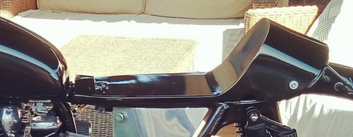
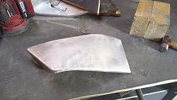
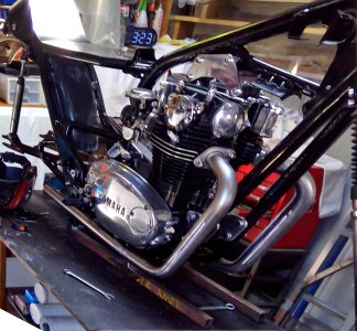
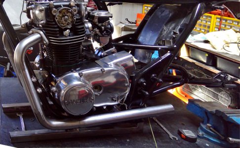
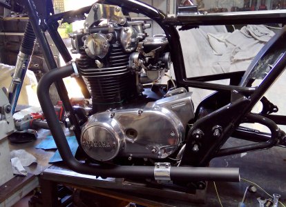
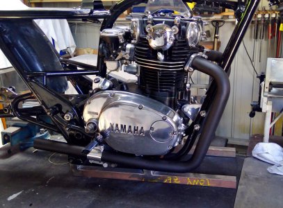
Exhaust pipes. I mocked up a pipe for the right side, welding together some exhaust pipe at the appropriate angles with the right amount of twist then took it to an exhaust centre and asked them to mandrel bend two bends from 42mm pipe to match the angles, so I could weld them together later. The exhaust guy assured me he could bend the entire pipe with the correct twist, then reverse it for the left side, so naturally I jumped at the chance to avoid welding the two bends together. Roll on five weeks, yep that's right, it took him five weeks, and I picked up the pipes and took them home. Well, what a balls up, the only thing that was correct was the twist. So, I cut both pipes around half way between the two bends, removed a 25 mm section and welded the two bends together. Problem! The bottom bend was way out, leaving the exhaust bending down toward the ground. To fix, I made a V cut in the pipe a few inches after the bend, bent the tail section up and welded the two pieces together. Repeating the process for the other side. Now, if you think exhaust pipe is round, it ain't! So twisting the pipes and butting them together leaves a few steps. So, I hammered them a little so they'd match up, welded them together and ground them smooth, then painted them with exhaust black pint.
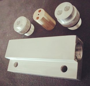
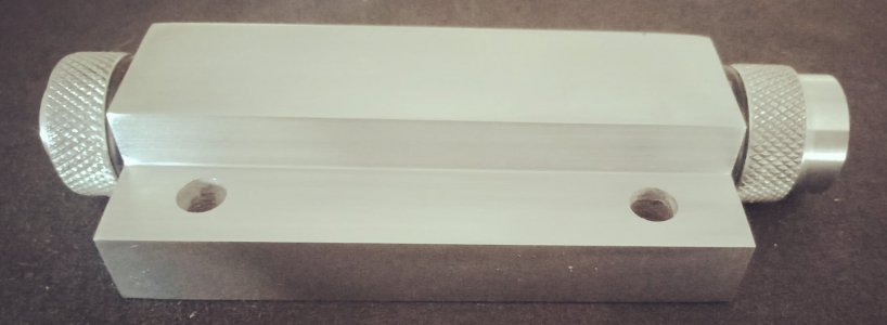
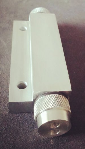
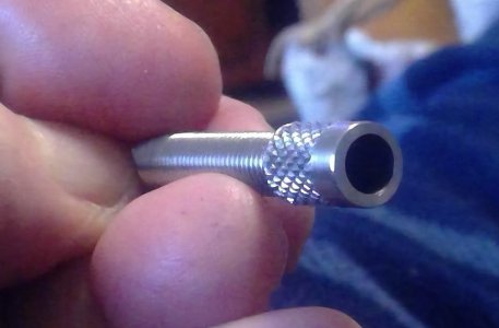
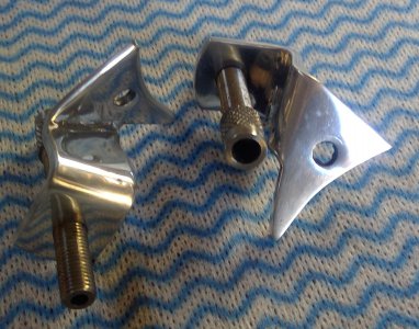
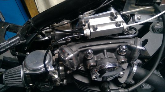
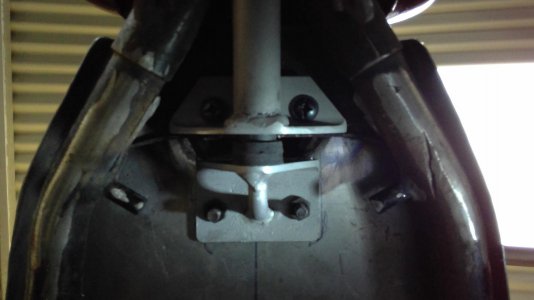
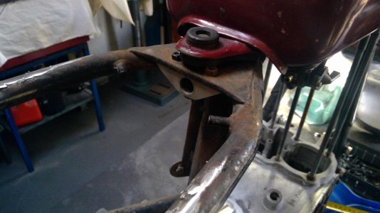
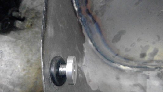
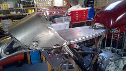
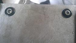
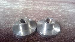
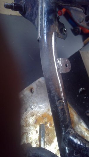
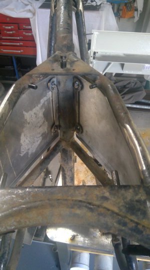
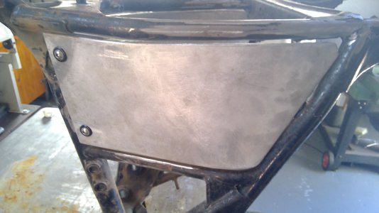
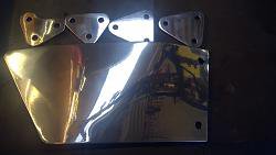
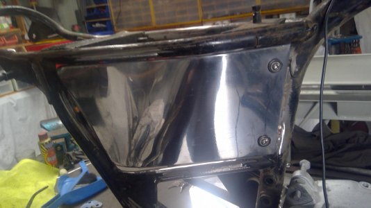
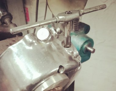
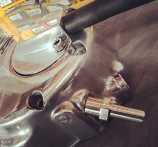
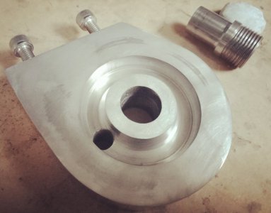
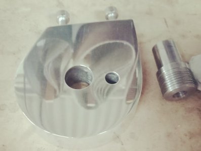
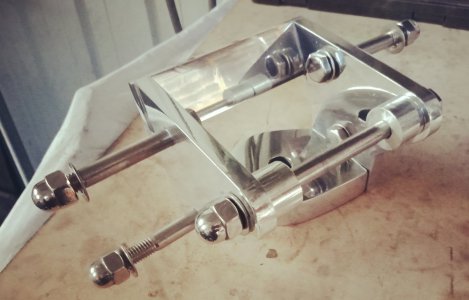
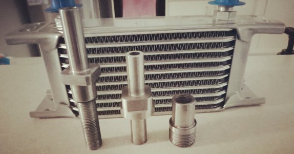
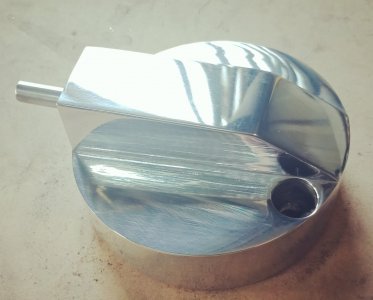
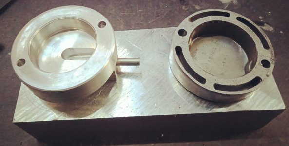
I mounted some 10mm thick ally in the four jaw, turned up the 42 mm hole, then marked the position of the 10mm exhaust stud holes drilled them through, shaped the clamps and polished them. For the lower mount, I bent up some 3mm steel plate in a half circle with short returns either side, shaped another 3 mm piece of steel to affix to the frame and welded it to the half circle clamp, then painted it exhaust black paint. Next I bent some 3mm ally plate in a half circle with returns each end, stuck it together with the steel half circle and drilled through four holes for stainless Allen heads, and polished the ally half clamps. The pipes have a very slight upwards sweep.
I mounted some 10mm thick ally in the four jaw, turned up the 42 mm hole, then marked the position of the 10mm exhaust stud holes drilled them through, shaped the clamps and polished them. For the lower mount, I bent up some 3mm steel plate in a half circle with short returns either side, shaped another 3 mm piece of steel to affix to the frame and welded it to the half circle clamp, then painted it exhaust black paint. Next I bent some 3mm ally plate in a half circle with returns each end, stuck it together with the steel half circle and drilled through four holes for stainless Allen heads, and polished the ally half clamps. The pipes have a very slight upwards sweep.
Attachments
-
 unpainted right pipe.jpg518 KB · Views: 32
 -
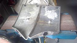
 unpainted left pipe.jpg490.2 KB · Views: 18
 -
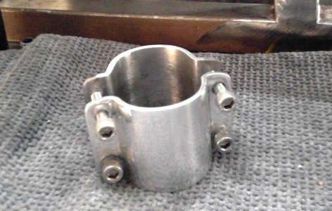 4 bolt exhaust bracket.jpg478.4 KB · Views: 13
 -
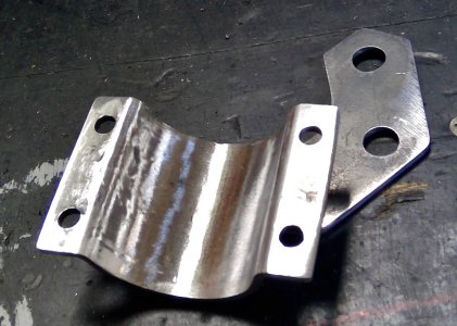 4 bolt exhaust bracket inner steel.jpg365.5 KB · Views: 14
 -
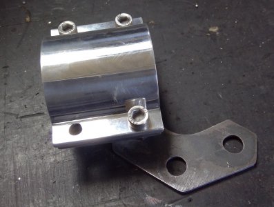 4 bolt exhaust bracket complete.jpg488.4 KB · Views: 12
 -
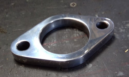 exhaust clamp1.jpg247.5 KB · Views: 15
 -
 painted exxhaust left.jpg877 KB · Views: 17
 -
 painted exhaust right1.jpg880.3 KB · Views: 21
")