-
Welcome back Guest! Did you know you can mentor other members here at H-M? If not, please check out our Relaunch of Hobby Machinist Mentoring Program!
You are using an out of date browser. It may not display this or other websites correctly.
You should upgrade or use an alternative browser.
You should upgrade or use an alternative browser.
Static phase converter wiring questions.
- Thread starter LEEQ
- Start date
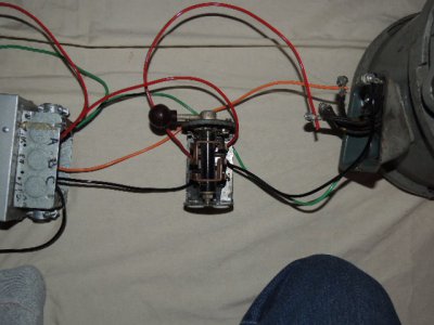
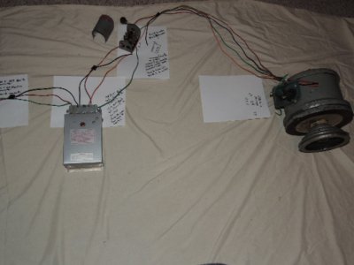
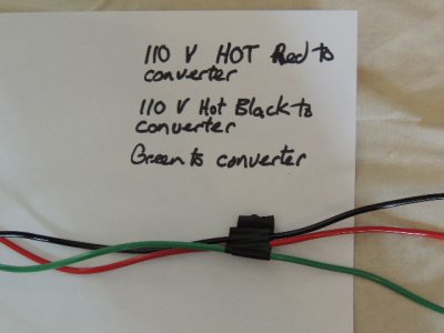
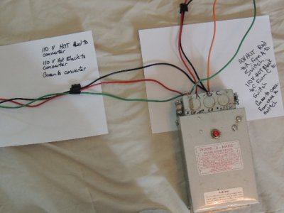
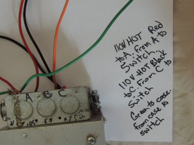
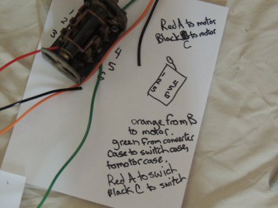
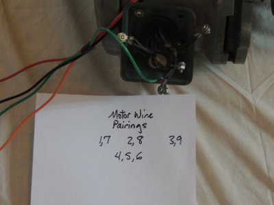
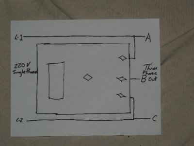
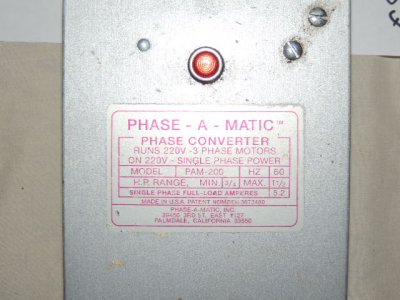
The phase converter directions show the diagram in the next to last photo. L-1 is a 110v hot leg going to terminal A on converter and on to switch to motor. I chose red for this lead. L-2 is a 110v hot leg going to terminal C on converter and on to switch to motor. I chose black for this lead. B is the leg that is used for starting the motor . I ran it straight from the converter to the motor. I chose orange for this lead. I grounded from case to case to case with a green wire. I ran Red A and Black C to the switch. I ran another Red A and Black C from the switch to the motor. I found the motor wires paired as in the 3rd to last photo. Phase-A-Matic shows no provision for wiring in the forward off reverse switch. As I understand it, if I switch Red A to Black C the motor reverses direction. My questions are these; 1 What positions do Red A and Black C wires from converter to switch go on the switch? 2 What position do Red A and Black C wires from switch to motor go on the switch? I assume 1,7 - 2,8 - 3,9 are the pairings I am going to attach Red A, Black C, and Orange B to. 3 Does it matter wich wire goes to wich pairing? 4 What do I do with pairing 4,5,6? Leave it tied together? I know this bport was wired with these components, I just don't know how exactly. I would be so relieved to find qualified help here. Thanks in advance.
- Joined
- Feb 2, 2013
- Messages
- 3,622
the phase converter directions show the diagram in the next to last photo. L-1 is a 110v hot leg going to terminal a on converter and on to switch to motor. I chose red for this lead. L-2 is a 110v hot leg going to terminal c on converter and on to switch to motor. I chose black for this lead. B is the leg that is used for starting the motor . I ran it straight from the converter to the motor. I chose orange for this lead. I grounded from case to case to case with a green wire. I ran red a and black c to the switch. I ran another red a and black c from the switch to the motor. I found the motor wires paired as in the 3rd to last photo. Phase-a-matic shows no provision for wiring in the forward off reverse switch. As i understand it, if i switch red a to black c the motor reverses direction. My questions are these; 1 what positions do red a and black c wires from converter to switch go on the switch? 2 what position do red a and black c wires from switch to motor go on the switch? I assume 1,7 - 2,8 - 3,9 are the pairings i am going to attach red a, black c, and orange b to. 3 does it matter wich wire goes to wich pairing? 4 what do i do with pairing 4,5,6? Leave it tied together? I know this bport was wired with these components, i just don't know how exactly. I would be so relieved to find qualified help here. Thanks in advance.
you are partially correct, if you switch any 2 of the 3 power leads you will reverse direction.
Question 1: You could use a rotary or drum switch wired in before the converter, if you switch the A and C, it would change the motor direction.
Q2: The wiring would depend on how you would like to accomplish the reversal of phases, a rotary switch could be employed if it is of sufficient capacity. A contactor circuit comes to mind as well... You can leave B connected to the motor at all times provided you had a switch to cut power off between L1 and L2
q3: No, it doesn't matter at first, you may change directions at any time.
Q4: Yes t4,t5,t6, stay together for running in the y configuration. 1,7 2,8 3,9 get paired up with a b c respectively.
A rotary/ drum switch is a good way and relatively inexpensive, but it's only one of a thousand ways to do the same thing.
I'm happy to help if you have more questions.
Mike
I kind of chopped up your post, and replied IN the post. Hope it makes sense. I think you've basically got it right, just be careful not to leave any exposed wire or connections.The phase converter directions show the diagram in the next to last photo.
L-1 is a 110v hot leg going to terminal A on converter and on to switch to motor. I chose red for this lead.
L-2 is a 110v hot leg going to terminal C on converter and on to switch to motor. I chose black for this lead.
B is the leg that is used for starting the motor . I ran it straight from the converter to the motor. I chose orange for this lead.
I grounded from case to case to case with a green wire.
I ran Red A and Black C to the switch. I ran another Red A and Black C from the switch to the motor.
I found the motor wires paired as in the 3rd to last photo. Phase-A-Matic shows no provision for wiring in the forward off reverse switch. As I understand it, if I switch Red A to Black C the motor reverses direction. (This is correct. Reverse any two power wires going to a three phase motor will reverse the rotation, with a phase converter it makes sense to switch the two "non manufacturered" legs)
You didn't indicate what kind of switch you were using. If its a multi-pole, three position drum switch, made for just this purpose, It'll be center switch position off, A, B, C from converter OPEN. One "ON" switch position will have A-A, B-B, C-C, the other "ON" switch position will have A-C, B-B, C-A. Any switch than can do that will work, as long as it will handle the current flow. Do NOT assume that because leg B doesn't reverse that you can leave it connected UNLESS you use some other method of disconnecting the power to shut it off. You do NOT want one leg hot when the machine is off!
My questions are these;
1 What positions do Red A and Black C wires from converter to switch go on the switch? (See above, sorry I can't draw a diagram, can't post pictures yet, too much lurking I guess)
2 What position do Red A and Black C wires from switch to motor go on the switch? I assume 1,7 - 2,8 - 3,9 are the pairings I am going to attach Red A, Black C, and Orange B to. (Exactly, and it doesn't matter which ones you tie to. A can go to one of those pairings, B another pairing, and C the remaining pairing. They won't need to change at the motor to reverse)
3 Does it matter wich wire goes to wich pairing? (Nope)
4 What do I do with pairing 4,5,6? Leave it tied together? (Yes, exactly, leave it tied together)
I know this bport was wired with these components, I just don't know how exactly. I would be so relieved to find qualified help here. Thanks in advance.
Three phase motors have one unusual characteristic different from single phase motors. If one "leg" is missing, it will still try to run on the other two legs. If it is trying to start that way, it will hum loudly, and draw very high current. If that happens, shut it off AT ONCE, you only have seconds before perminent damage can happen. If it happens to be running when you lose a leg, it may continue to run (very reduced power, with increased current draw, and heating windings), especially if only lightly loaded, until such time as the load becomes too much for the two phase legs to carry, at which point it will stall, hum, and VERY quickly overheat. Watch for those symptoms while setting things up. If it "sounds" right while running, it probably IS right.
Ruben
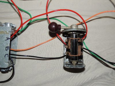
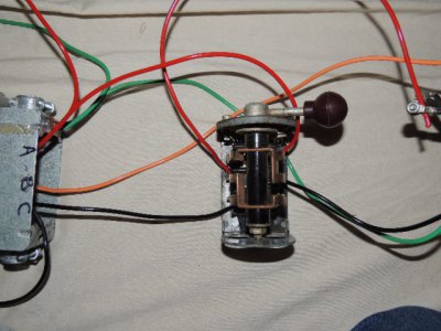
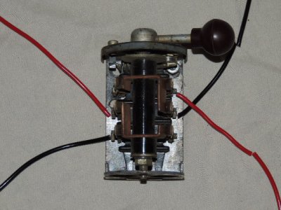
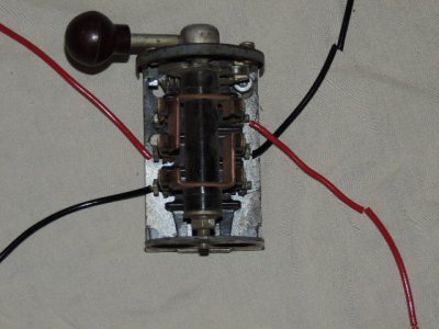
I think I have the switching figured out. I'm using the drum switch in all my pics. If I wire as shown in the pics in this post, switch to the left will be forward. Middle will be off, and right would be reverse. when the handle is to the left the red goes to red and black to black. when to the right, the opposite is true. Am I looking at that right? Also, I switched the red and black because the orange is the leg made by the converter.


- Joined
- Feb 2, 2013
- Messages
- 3,622
after pondering it for a minute...
1) black from motor 4) not used
2) line A 5) line C
3 not used 6) red from motor
comes to mind....
mike )
)
1) black from motor 4) not used
2) line A 5) line C
3 not used 6) red from motor
comes to mind....
mike
Last edited:
That will work perfect. Note that phase B isn't being switched, nor can it be with that drum switch, so the safe play would be to use this drum switch only for reversing, and use a two pole toggle switch on the input of the converter for off-on, UNLESS you have a three pole contactor between the converter and the motor that breaks the leg B.after pondering it for a minute...
1) black from motor 4) not used
2) line A 5) line C
3 not used 6) red from motor
comes to mind....
mike)
Having leg B "hot" during the off cycle would "work", just wouldn't be safe.
Ruben
I would probably just use the breaker as I just want to test the motor and do very little work with this set up. If this works, I want to go vfd for full power and speed control. Ulma, I'm afraid you lost me with your last post, but I think I have the gist of it.
Ok, so I think I have this right. red goes to A to switch to pair 1,7. Black goes to C to switch to pair 3,9. Orange goes from B to pair 2,8. When switch is in forward, red goes to red, black goes to black. When switch is in reverse red goes to black, and black goes to red reversing the motor direction. If you can't tell in these pics, I wired the switch as I proposed in the last set of photos. Am I tracking?
