Steam Engine Mistake Repair

Use an end mill to cut the new holes cutting straight down like you would with a drill bit. A drill bit will bend to the side and make a tapered hole to one side. Leave it like it is and put a washer under the head of the bolt. No one will see it once it is put together and for a small model, strength is not a concern. You could even part off some brass washers that will cover the over size double holes. A little extra brass could dress it up the looks.

Good luck.

D

Thought about that one too and was about to do just that, but my buddy requested a repair rather than a cover up job.
 
There is a theme of screwing stuff up on this engine after not reading the print carefully enough. It is a hard lesson to learn.
 
It is easy to make mistakes. Almost everything I have learned in my life was by MISTAKE.

D
 
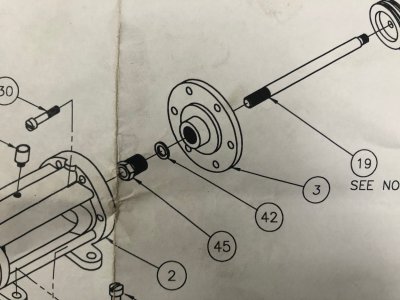
Ok...... so being the obvious “newbie” on the thread I have some questions. I looked at the original drawing. Are the holes in the 1 and 4 O’clock positions the ones that are out of alignment? I ask this becaus as a newbie I would have looked at the drawing and seen 6 holes all equally spaced and just commanded my DRO to make it so, and “voila”; which would have been wrong.....

Would somebody (if you don’t mind taking the time to do so) show me what went wrong and why. Thanks guys!

Derek.


Sent from my iPhone using Tapatalk

Derek,

You are correct, the holes at the 2, 4, 8, & 10 o'clock positions (Qty. 4) are the holes which are not evenly spaced on a bolt circle relative to the 12 & 6 o'clock holes. You could easily miss this (as I did) by noting the 2.312 DIA BC callout and assuming they were evenly spaced, however the dimensions on the print do correctly show you where to place the holes if you pay attention to it.

Like you described, I set up the bolt hole circle wizard on my CNC and let her rip, not realizing the error until after the drilling was done. They are close enough to evenly spaced that you don't notice it visually super easily.

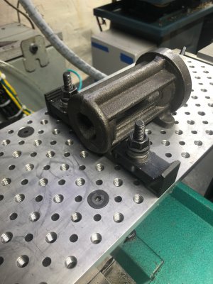
The reason this is designed this way is that there are screws that come from the outside of that flange (facing down towards my machine table in the picture) that pass through this part, through the cylinder head, and finally thread into the cylinder casting. The screws have a head on them that is wider than the thread (like every screw) so the bolt holes need to be located far enough from any features on the casting that would get in the way of the bolt head. If the holes are evenly spaced, the screws hit ribs on the casting.

As mentioned above, the drawing could have depicted these holes in a different way as to avoid the risk of confusion.

The ribs are visible in the photos below.
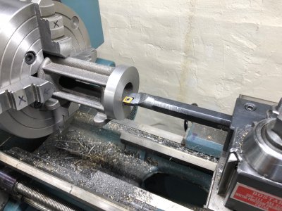
image021.jpg

image014.jpg

image075.jpg
 
They are close. I almost screwed it up on the other parts too! I agree with the drawing being a poor style. If I see the abbreviation "B.C." then I automatically assume evenly distributed. Probably not the best thing to do.

Ugh fine... I really don's want to drill or tap the screwed up holes, but you guys are convincing me. Probably tap 1/4-20 and run a die over the cast iron "pins" to turn them into studs. Would make setting the depth easier too rather than press fitting them.

That, to me, sounds pretty risky. Drill and tap, make plug, machine off flush, ect. Lots of places to make a bigger mistake. With my luck, the plug would come loose while cutting the new hole, twist sideways, bind the cutter, and split the casting and break off the end mill in the work. Or at the very least I would break off a tap in the hole and bugger up the works trying to get the tap out.

D
 
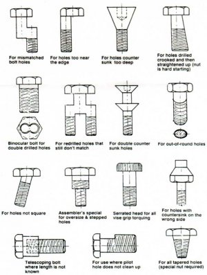
Maybe something like the this? The top left one looks like it might work or the bottom center one. Just kidding! I am sure you will come up with a workable solution.
 

Attachments

  • sillybolts001.jpg
    sillybolts001.jpg
    97.7 KB · Views: 19
Maybe something like the this? The top left one looks like it might work or the bottom center one. Just kidding! I am sure you will come up with a workable solution.

I love that graphic! I'm good as long as I don't end up needing the 6th one.
 
Thanks macardoso for the explanation. Lots of respect as always to the group for your cumulative patience and wisdom. And to Twirpunky for what will be a new wall hanging in my shop..... or rather a pictorial means of explaining to my wife how I plan to fix what I have just screwed up/created in the shop.


Sent from my iPad using Tapatalk
 
Back
Top