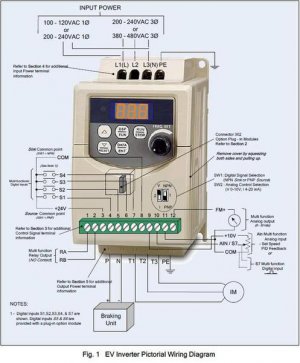
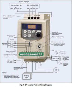
Stupid VFD setup questions that I really want to know....

HMF

Site Founder
Administrator
Joined
Sep 22, 2010
Messages
7,223
There are several things about setting up a VFD that I want to know:

1- Is there any benefit to running using single phase 220 and a VFD that converts single phase 220 to three phase 220
as opposed toa VFD that converts single phase 110 to three phase 220? What if anything is the difference?


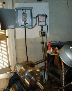
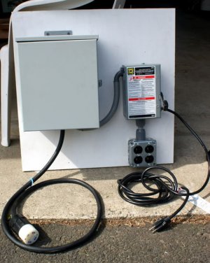
Next, I need to ID the components in this setup:


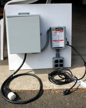
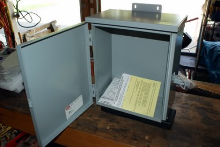
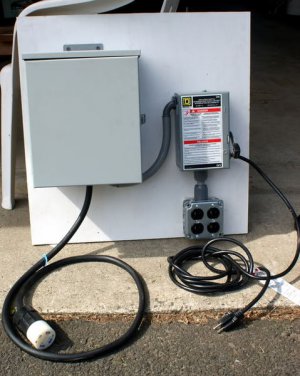
View attachment 33695
Looks like a fused disconnect (knife) switch connected to an outlet block and a corded grounded plug coming out of the disconnect.
I don't understand why use a corded plug if the disconnect is connected to a terminal block?
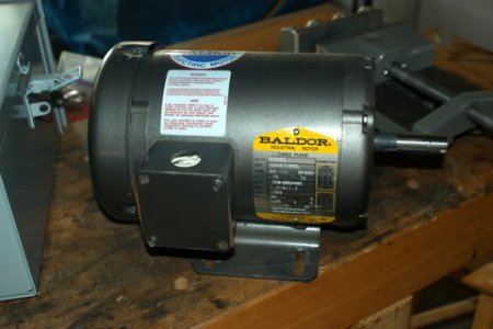
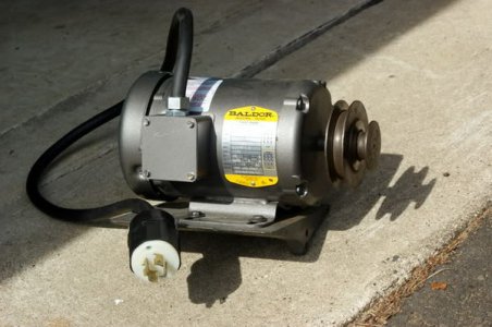
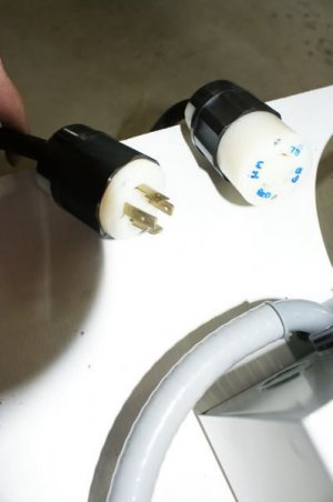
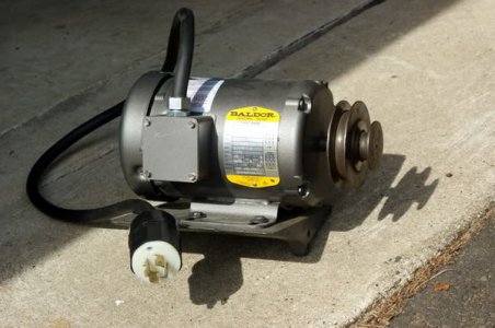
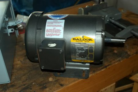
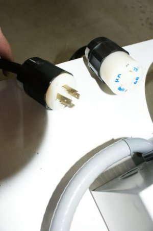
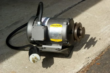
The cord coming out of the VFD is three phase twist plug and there is a female which connects to the male on the motor.
Why do it this way instead of a permanent hookup?

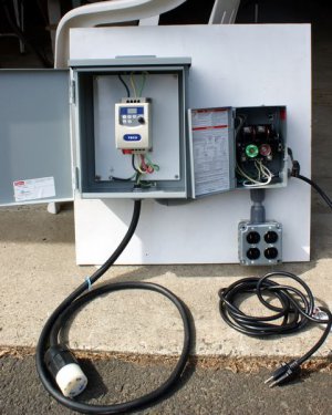
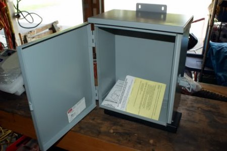
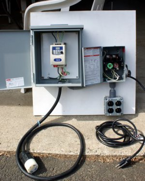
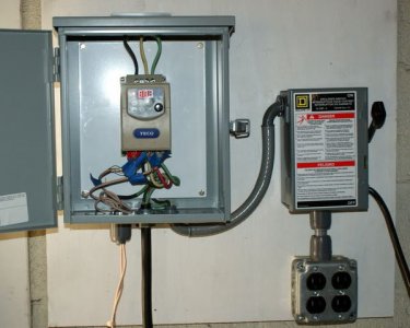
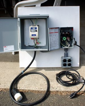
View attachment 33696

This shows the fused disconnect. Why is there a plug AND connection to a terminal block?
Where do you plug in to- not the terminal block. What is the purpose of the terminal block?

What type of connectors are those between the disconnect switch and terminal block (they look tapered).

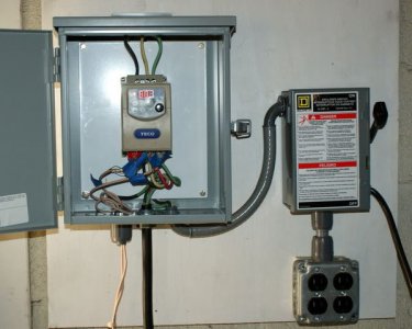
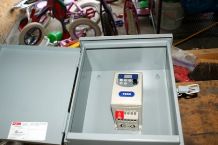
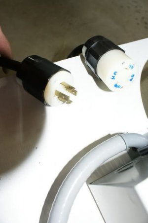
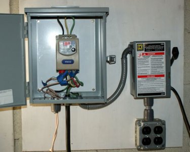
View attachment 33697

What are the wires that are taped with blue tape here?

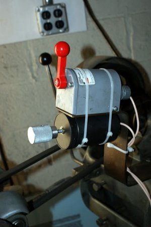
Do these go to the drum switch?


Thanks for answering my stupid questions.

Can someone show the setup of the remote controls, including an Emergency Kill (off ) switch?


:tiphat:Nelson
 
Using 220 instead of 110 Allows the use of larger equipment with larger electrical loads vs 110 that will limit you to lower amp draw. Easier to run 2 hp on 220 than on 110.

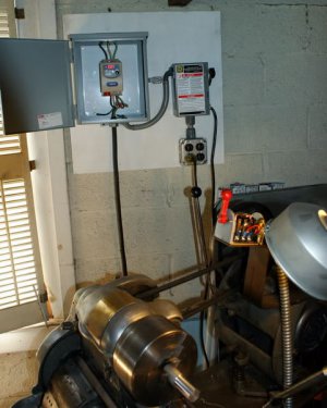
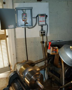
Seems that this setup is portable instead of being fixed as you will likely do in your basement, oops lower level!

The blue tape is likely marked with something to help in wiring the unit. Letter codes or numbers etc. likely for remote controls ie forward, reverse, run and stop. On one rolling mill at work I have setup motor controls with run, stop, forward, reverse and a pot for speed. Work great. On the subject of emer stop, the mill that I setup has brakes, so as soon as you hit the stop button it stops. There is no braking delay.
 
Last edited:
For forward and reverse all you need is a SPDT Switch from Radio Shack. The switch does not carry any real power, it is just used to change the state of the logic in the VFD Unit. The pot will be specified but likely 5 or 10 kohm. The run/stop look for stuff like the switches shown on pg 3676 in the MSC catalogue. I like using illuminated run switch, shows that you are hot.
 
Hi Nelson,

Those pics and set up come from the PM site.
The guy that did the set up did a great write up about it.
I am most likely going to base a lot of my set up around what he did.

From what i remember:
Designed to be portable, that is why the 3 phase has a plug on it.
The blue tape was to ID the wires and make life easier when connecting it all.


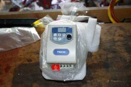
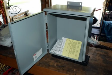
Here is the cost so far and a few pics to get started:

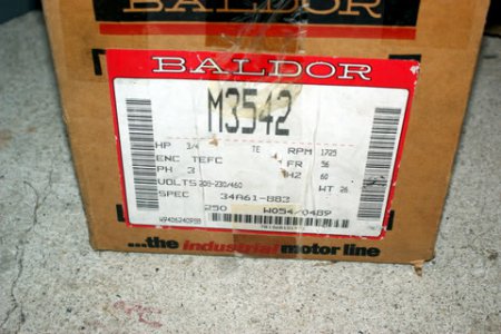
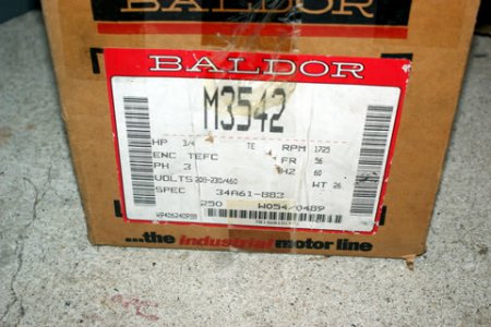
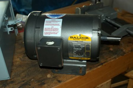
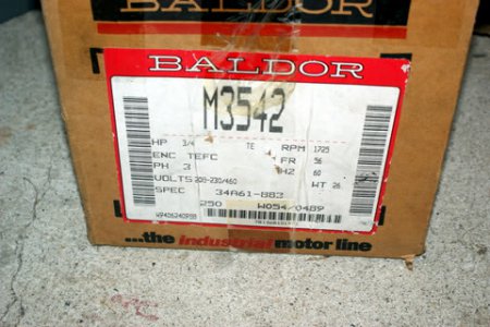
$69.89 Delivered : New Baldor 3 Phase 3/4 HP M3542 Motor w/ 56 Frame (Auction)

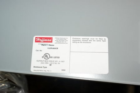
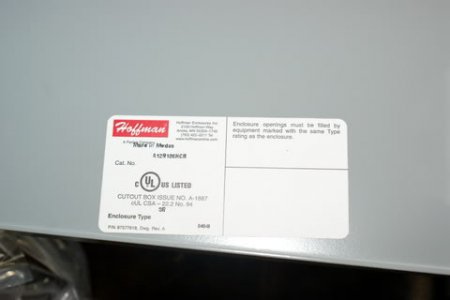
$24.90 Delivered : Hoffman Electrical Box 12"x10"x6" (Auction)

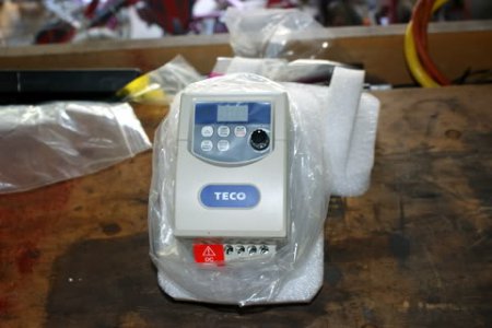
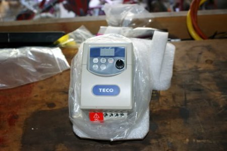
$145.71 Model JNEV-101-H1, Single Phase Input ONLY, Three Phase Output ( Dealers Electric )

1.jpg

2.jpg

3.jpg

4.jpg

5.jpg

6.jpg

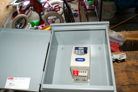
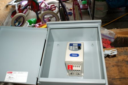
The install went well, the teco vfd was very easy to wire up. Added a switched outlet to my panel for a light and such. The panel and motor connection are portable at this point as I hope to remodel garage in the future. The operation is the vfd/motor is flawless at this point, smooth and quiet operation.

I am going to reuse the original fwd/rev switch to remote operate the vfd and add a remote POT for speed control.

Pics tell the story.
7.jpg

8.jpg

9.jpg

10.jpg

11.jpg

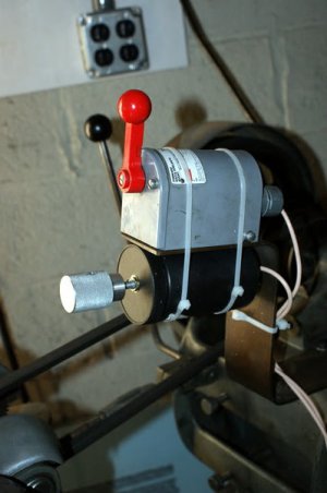
I used the old drum switch to operate the FWD Stop REV.

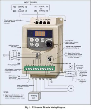
Terminal ID for Drum Switch was
S1 = 4 - FWD
S2 = 5 - REV
COM = 8

Set Function F04 = 001 Turns on the external drum. 000 was the default. 3 Wires needed.

Used some thin gauge wire I had around.

The speed control was a Radio Shack 10K-Ohm Linear ( not Audio ) Taper Potentiometer part # 271-1715 $3.50 at the local store. I used a plastic bottle with lid to hold it and zip tied it securely below the drum switch. I had it in my junk and I meant to change it out with a metal box but I never got around to it.

Terminal ID for the POT speed control was
+10 V = 9 First lead POT
AIN = 10 Center lead POT
COM = 11 Last lead POT

3 wires needed for this as well.

Set Function F05 = 002 Sets Frequency to the External POT.

If your POT speed runs backward just reverse the 9 and 11 leads and the speed increase / decrease should reverse, in my case turn to the right go faster then left to go slower.


I used some tape to number/mark the wire for the connections. A few minutes to hook them up and I was running.

It runs like a dream in operation, I throw the power switch up and just open the door the watch the Frequency/Speed. I did use the set screw on the speed knob to index the POT so at the straight up position the frequency setting is approx. 60. The other setting I changed from default were setting the max frequency to 100 so my range is 5 to 100. I did lower the deacceleration value to 1 second from I think the default of 2.5 seconds.

These were from my notes but please check the manual yourself.

Thoughts and Comments Welcome


vfd12.jpg

vfd13.jpg

vfd14.jpg


Square D 30-Amp Fusible Metallic Disconnect

Item #: 92606 | Model #: L211N $14.12
120/240 vac
Metal Indoor Enclosure
Horsepower rated 3 HP @ 240 vac
Neutral bar included

Lowes.com

This was done by Lost Pup.

Andrew

1.jpg

1.jpg

2.jpg

2.jpg

3.jpg

3.jpg

4.jpg

4.jpg

5.jpg

6.jpg

5.jpg

7.jpg

6.jpg

8.jpg

7.jpg

9.jpg

8.jpg

9.jpg

10.jpg

11.jpg

10.jpg

vfd12.jpg

11.jpg

vfd13.jpg

vfd12.jpg

vfd13.jpg

vfd14.jpg

vfd14.jpg
 
Last edited by a moderator:
I wanted to try to understand the setup in the photos, but didn't know how else to ask.

I don't understand why he used plugs, and what the four recepticle outlet is for.
You could just as well disconnect wires without plugs and cap the wires off.
It looks like he is using 110V in, but from what Pierre says, 220 would be best.

Is the conduit between the VFD box and disconnect plastic watertight conduit?
What about the connection from the receptacle to the disconect?


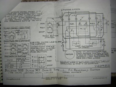
Someone did a diagram for me to use the original Westinghouse button box, but,
there wouldn't be any variable speed if I used that- just on-off-reverse, and I would have to have
relays which I bought to keep the power on since the buttons are momentary contact.

Nelson
 
Since it is portable, mutliple machines, and the 110 plugs for lights etc. the conduits appear watertight versions to me.
 
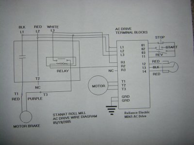
Nelson, when I get to work tomorrow I will look at my schematic for the rolling mill. I had to draw it from scratch to replace the old contactors that were unserviceable. It maybe of use to us as well.
 
Nelson, when I get to work tomorrow I will look at my schematic for the rolling mill. I had to draw it from scratch to replace the old contactors that were unserviceable. It maybe of use to us as well.

Thanks, I had a box of old contactors (Clark something) that came off the machine originally.
I removed all the wiring when I bought it, figuring I'd change it anyway.

Nelson
 
Here are 2 pictures of the wiring

Nelson
Second one is the old wiring of the mill. May be useless but how knows. The first is the current wiring of the mill using a VFD from Reliance Electric. It shows the run stop and f/r and speed pot. It will not be exactly like any other maker but the idea is there. You can ignore all the stuff on the left side as it is for the motor brake.
Pierre

new-wiring-diagram.jpg old wiring diagram.jpg View attachment 95166
 
Back
Top