Tachometers with hall proximity sensor question

I'll be more specific. You want your magnet mounted on the spindle. It is the spindle rotation that you are concern with. If you mount the magnet on any gear or pulley other than the spindle, you will get a RPM reading of that gear or pulley that probably is not the spindle RPM.
There is no place on the spindle itself to mount it to.
 
Hall effect sensors are "better" in that they always produce the same size (voltage) signal regardless of magnet/metal speed, but do have the downside of having to supply a separate supply voltage to the sensor.
 
There is no place on the spindle itself to mount it to.
I think I understand your problem. Give us the make and model of your lathe. Send pictures of both chuck end and pulley and/or gear end of the spindle. With that, someone might be able come up with some ideas.
 
I think I understand your problem. Give us the make and model of your lathe. Send pictures of both chuck end and pulley and/or gear end of the spindle. With that, someone might be able come up with some ideas.
It will be used on my milling machine.
 
I believe OP is asking about a mill. If it’s a BP or clone, the pulleys (in a J head) are not necessarily the spindle speed. It depends on whether the back gear and cam ring are engaged.

In theory you could put the magnet on the spindle bull gear, with the sensor inside the gear housing.
 
I was assuming that we were talking about a step pulley setup on a lathe... in which case the step pulley is not keyed to the spindle... the spindle is driven by the bull gear pin when not in back gear, or by the backgear when the backgear is engaged. When the backgear is engaged, the spindle is 'under-driven' and is turning slower than the step pulley.

I am fairly sure that most milling machines that have a back gear will be the same. Mine is... when I engage the 'lower' gear range on the head (which is a back gear setup) the spindle is turning slower than the step pulley.

You should verify whether your mill is designed this way...

-Bear
 
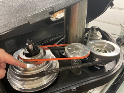
Sounds like we all just have a different picture in our heads. Here is the spindle step pulley on my mill. Keyed to the spindle and always turning at the same speed as the spindle. For my mill I could put the magnet where my finger is or anywhere else on that step pulley that would allow me to mount the sensor opposite and I would get spindle RPM regardless of where I positioned either belt. The step pulley and spindle will always speed up and slow down together with belt adjustments.

Guess we will have to see a pic of what @Suzuki4evr has.
 

Attachments

  • B6B02C07-7FBA-4253-BD2A-91FFA900C96F.jpeg
    B6B02C07-7FBA-4253-BD2A-91FFA900C96F.jpeg
    3.2 MB · Views: 21
OP, you are correct, Sir. I had a picture in my mind of a smaller machine without back gears. It will be necessary to get "ahead" of the back gears to track spindle speed. On a lathe, start with the chuck, collet, center. That's what is necessary to control. Work back from there looking for a place to mount the magnet. For a milling machine, there are fewer locations available but the process is the same. The final location must be before any gearing.

Way back when "cruise control" first appeared on automobiles, there were kits available to retrofit earlier models with cruise control. Speed control wasn't all that accurate, some kits would surge and some had a wide speed differental. Typical mounting of the magnet was on the drive shaft, just aft of the front U-joint. With the coil / sensor hanging from the transmission or drive shaft tunnel.

The mounting process was to clean (well) the drive shaft where the magnet was to mount. The magnet was then stuck to the drive shaft through its' own magnetism and held in place with tape. The specific tape was "packaging tape", a clear (Mylar?) tape with nylon strands. The stuff that's hard to cut and impossible to break by hand. I don't know the proper name but it is still widely used. If used on a clean surface, it is essentially oil and grease proof once applied. If used on a greasy or dirty surface it doesn't stick worth a damn. About like a worn out shoestring.

Used on a machine tool, a similar technique could be used. The spindle must be clean and oil free when taping. But opens up the possibility of mounting the magnet internally to the case / frame. Mounting the sensor might be more difficult, some machines use every cubic inch of internal space. Space between the magnet and the sensor isn't necessary to set with a feeler gauge. A paper match stick will serve. A "Hall Effect" sensor is more sensitive than a coil. A sharper leading and trailing edge. But also more directional. Which shouldn't matter in this application. But nice to be aware of.

.
 
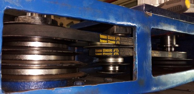
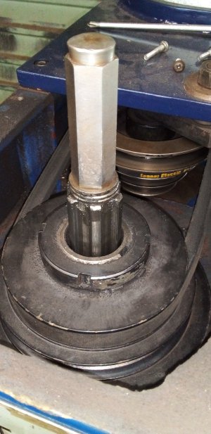
Here is what I have to make things clear. As you can see,there is NO place on the spindle itself,only on the spindle stack pulley.20210901_082812.jpg20210901_082721.jpg
 
Back
Top