Tail Stock Alignment

You are one step ahead of me RJ. I JUST finished skimming a 10" faceplate a few weeks back on the old headstock setting. Once I'm happy with the lathe setup, yes will have to check the plate & likely give it a light re-surface. It wasn't an onerous job, but the cast iron powder seems to get everywhere. Going to lay down some lightly oiled paper towels or something.

So my story is still a bit open ended until my accurate level arrives to validate lathe twist status (the leg jacking rigmarole). But is the proper sequence like what Tom Lipton shows:
- adjust lathe level (twist)... but within reasonable limits
- if still cutting taper, zero lathe twist & proceed to headstock

Reason I ask is I got thinking about this bed twist issue, if done in isolation as a cure. If the dumbbell test cutting is always confined to relatively short length of the test bar, say 10". And you kept twisting the bed until taper was removed over that 10", couldn't you end up with a piece of licorice extrapolating the twist angle out the remaining 30" of bed or whatever?
Like you, I am awaiting the acquisition of a machinists level to refine my alignment.

Since I have no way, aside from headstock rotation, of aligning cross feed ways to the spindle axis, I will probably do that second, after leveling. My Grizzly 602 lathe has only two mounting bolts, under the spindle axis at the headstock and tailstock. It is my belief that when I installed the lathe, I pulled the lathe to my home-built table and distorted the casting.

Noticing a taper similar to what you observed, I rotated the headstock which eliminated the taper but now I cut a domed face. The correction that I made for taper is virtually the same as the misalignment that I am observing in the cross feed. In other words, I have used two wrongs to make it right.

My latest thoughts on alignment are that I should loosen the two mounting bolts to relieve stresses. My first adjustment would be for headstock rotation, as indicated by flatness of a machined face. The reasoning for this is the carriage is not moving along the ways so the effects of any twist would be minimal. Once the spindle axis is perpendicular to the cross feed ways, I would level the lathe bench, using the adjustments on bench feet, and then the lathe, using shims. Finally, I would check for taper, using Rollie's Dad's method and adjust shims under the headstock and or tailstock. The shims under the headstock end would be equal front to back and used to correct a vertical tilt in the spindle axis. Shims under the tailstock end would be to correct for twist.

There is also possibly a horizontal and/or vertical misalignment of the tailstock quill to the spindle axis which could be a combination of radial and angular misalignment. I would check that by mounting a test bar between centers and using the RDM method again. Checking with the quill retracted and the quill extended should pick up any angular alignment issues.
 
Coincidentally Keith Fenner just posted a YouTube video on very similar headstock re-adjustment procedure I went through (notwithstanding his unfortunate oil drain PITA). YouTube title is: Let's Look Under The Old Girls Apron Part Eleven. I think that MT5 straight bar is the cats meow.
 
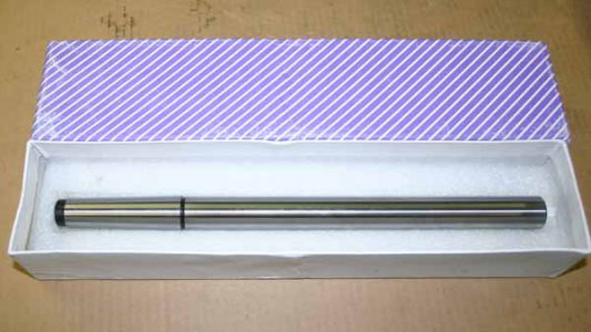
So just some closure on my lathe alignment issues. From ebay seller toolsforyou2015 I bought a ground test bar with MT3 on one end & straight cylindrical section on the other. They claim max-runout = 0.0001". Since I have no sure way to verify that, I'll just say 'ok'. :) There are multiple sellers of these (or N-Am re-packagers) at ranging prices for what I suspect might be the same thing because they all seem to come out of India. Notwithstanding the obvious ones that state made in USA/whatever. This one happened to be the least expensive for the longest length offered at 335mm total (just over 13").

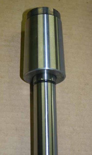
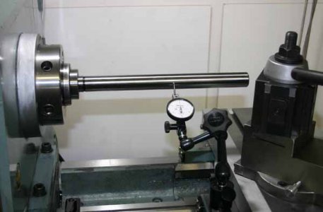
My lathe spindle is MT5 ID & it came with a ground MT5/MT3 adapter socket. Again, I have no idea how concentric or accurately the socket its ground taper wise but that's what was assembled. I saw a smidge more DTI deflection at the very outboard end compared to my last setup on a shorter bar, but depending on how I insert/twist the test blank/socket & hold my breath & phase of the moon... its within 0.0005". I rotated the blank to measure different quadrants & got the same results. So for the ease of setup & accuracy level I intend to work to, calling it good. As mentioned, the whole lathe levelling (twisting) was an unnecessary side show in my particular case that actually complicated matters.

With the headstock now established parallel to the ways, I set up the Edge tail post checker on centers & verified the tailstock is good to go, also within 0.0005". I didn't take a pic of this, I just replicated the video/instructions. I noticed a very slight change when I extended the tailstock quill out but that may well be re-clamping variation. Unfortunately with these 2 new validation tools, you use once to get everything aligned & then shelf them for a while. But I guess when you need them, you need them.

Getting back to the MT3 blank, an interesting observation. With DTI registered on the blank, as I hand wheel traverse down the blank longitudinally either way, you can see the needle float back & forth a couple thou across the zero mark. If I stop traversing, it ends up very close to zero. If I push or pull on the carriage, its pretty tight, maybe I can move the dial slightly ~ 0.001" but it seems to return. If apply ever so slight friction with the carriage clamp, it dampens needle twitch, but it still oscillates. I think what its picking up is some side junk momentum movement of me cranking on the handle or maybe play in traversing gear/rack? What I didn't do, but maybe should try, is power traversing & watching needle, maybe that would be smoother just lead screw driven? What I'm getting at is when we use the dumbbell cut test bar method & measure diameter difference between resultant headstock side & tailstock side dumb bells, we 'assume' there is no other junk movement introduced by the carriage movement or vibration or whatever (over & above surface finish & tool tip cutting dynamics). I'm really not sure now, but I'm kind of favoring this test bar method. Seems to be so rapid to set up & eliminates some of the 'cutting' potential variables?

IMG_5729_edited-1.jpg

IMG_5728_edited-1.jpg

IMG_5727_edited-1.jpg
 
Back
Top