- Joined
- Aug 22, 2012
- Messages
- 4,100
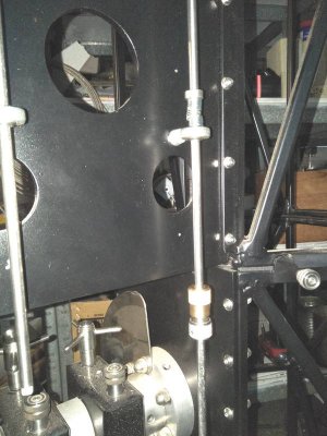
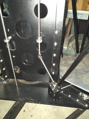
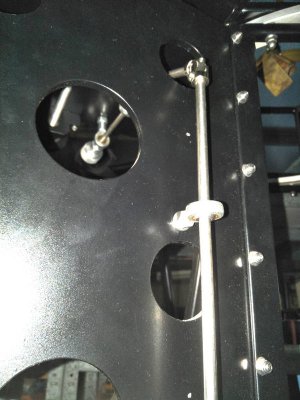
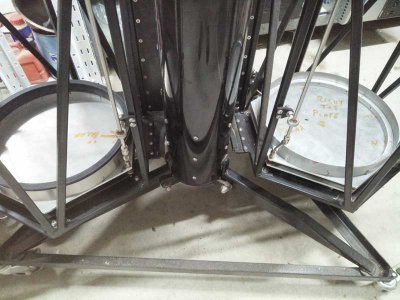
Obviously these long control rods will have to be separable (is that a word?} at the join of the two halves of the bino.
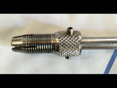
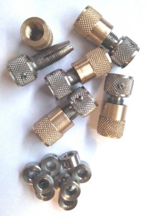
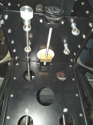
So I came up with this idea. This is a proof of concept and also to check on the orders of work as I need 8 of them.
The end of each rod will have a tang on one and a slot on the other, the stainless threaded part will be split along the taper into 4 (once I make a slitting saw arbor) the brass part has an internal taper to squeeze the split taper onto the other shaft and hopefully hold it tight.

the flange of the stainless part will have a grub screw to hold it tight to the rod.

After checking this out I think I will make the stainless part longer to allow a knurled section large enough to hold and twist giving a bit more torque to tighten them together. They should only need a half turn to lock.
The tongue and groove join meets in the centre of the stainless part so they cannot part sideways.
The top half of the rod will be spring loaded so it retracts far enough that the end with the tongue is higher than the base of the top tubes so hopefully they wont be damaged when the top half is placed on the ground.
All this so there is less chance of loosing bits in the dark.
So I came up with this idea. This is a proof of concept and also to check on the orders of work as I need 8 of them.
The end of each rod will have a tang on one and a slot on the other, the stainless threaded part will be split along the taper into 4 (once I make a slitting saw arbor) the brass part has an internal taper to squeeze the split taper onto the other shaft and hopefully hold it tight.

the flange of the stainless part will have a grub screw to hold it tight to the rod.

After checking this out I think I will make the stainless part longer to allow a knurled section large enough to hold and twist giving a bit more torque to tighten them together. They should only need a half turn to lock.
The tongue and groove join meets in the centre of the stainless part so they cannot part sideways.
The top half of the rod will be spring loaded so it retracts far enough that the end with the tongue is higher than the base of the top tubes so hopefully they wont be damaged when the top half is placed on the ground.
All this so there is less chance of loosing bits in the dark.


