- Joined
- Feb 15, 2020
- Messages
- 375
I faced the inner surfaces of the bearings.
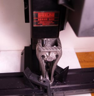
Alternate use for that boring bar I purchased for this build is between the frame and the hold downs.
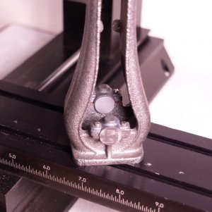
It had to be done anyway but I was hoping it would make the boring go a bit smoother. Here is my setup for that job. The tail stock is just there for reference to line it all up. It was out of the way when I was working.
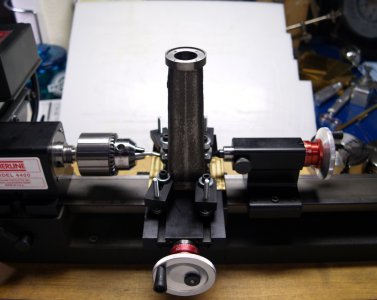
I would like to say it went well. What I didn't expect was some misalignment with the lathe headstock. It turns out that the farther away the work gets from the spindle, the end of the tool (drill, reamer) goes higher than the tail stock center. I checked it with dead centers in the spindle and tail stock and they were very close when tip to tip, but 9" out the center of the reamer was about 1/8" above the tail stock center. I still need to investigate this further. While I was doing the job I thought the tools were flexing or the caps were much softer than the frame so I corrected the best I could by adjusting with shims. In the end the bore climbs about 1/64" from one end to the other. It did seem like a good idea at the time, but I would probably have had better results on the mill.
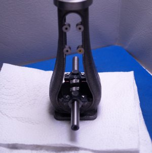
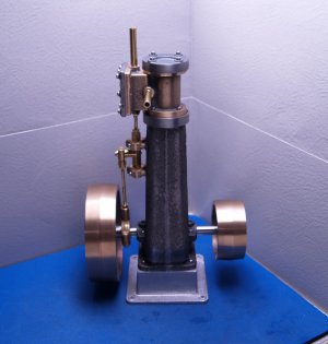
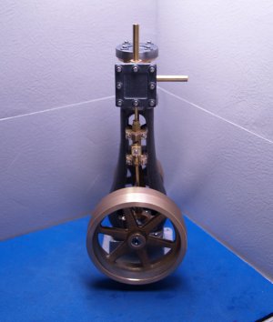
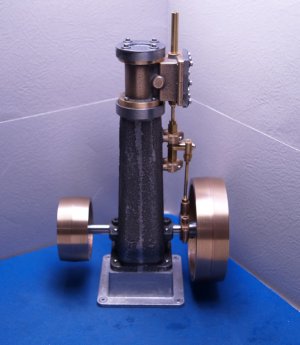
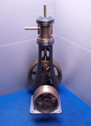
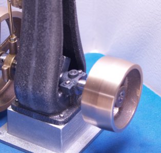
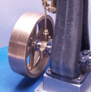
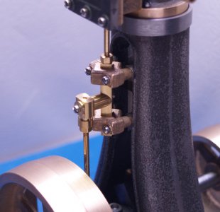
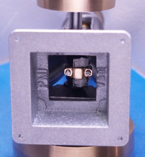
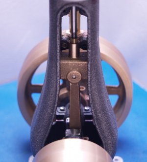
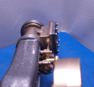
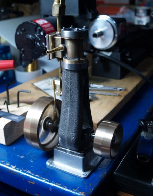
Anyway the crank is in and it turns freely. Just a few more holes to drill to mount it to the base and I can try to make it run.
Eric

Alternate use for that boring bar I purchased for this build is between the frame and the hold downs.

It had to be done anyway but I was hoping it would make the boring go a bit smoother. Here is my setup for that job. The tail stock is just there for reference to line it all up. It was out of the way when I was working.

I would like to say it went well. What I didn't expect was some misalignment with the lathe headstock. It turns out that the farther away the work gets from the spindle, the end of the tool (drill, reamer) goes higher than the tail stock center. I checked it with dead centers in the spindle and tail stock and they were very close when tip to tip, but 9" out the center of the reamer was about 1/8" above the tail stock center. I still need to investigate this further. While I was doing the job I thought the tools were flexing or the caps were much softer than the frame so I corrected the best I could by adjusting with shims. In the end the bore climbs about 1/64" from one end to the other. It did seem like a good idea at the time, but I would probably have had better results on the mill.

Anyway the crank is in and it turns freely. Just a few more holes to drill to mount it to the base and I can try to make it run.
Eric
Last edited:


