-
Welcome back Guest! Did you know you can mentor other members here at H-M? If not, please check out our Relaunch of Hobby Machinist Mentoring Program!
You are using an out of date browser. It may not display this or other websites correctly.
You should upgrade or use an alternative browser.
You should upgrade or use an alternative browser.
The Journey Begins, PM Research #5.
- Thread starter EricB
- Start date
- Joined
- Feb 15, 2020
- Messages
- 375
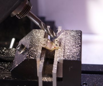
Cutting the grooves for the valve slide. I've found a lot of different methods and fixtures other folks used for doing this on the web. I decided to just rotate the head stock 45 degrees, hold them in the vise, and use an end mill. I don't have angle blocks or a sine bar so I used what I have to set the angle.
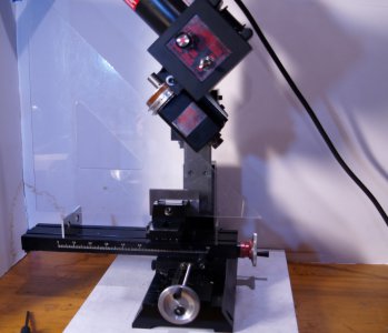
I just knew that old drafting triangle would come in handy some day.
After that and moving the vise it was just a matter of cutting the grooves. First the bearings.
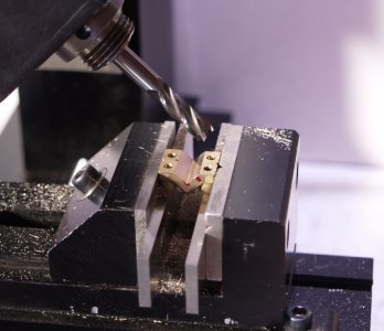
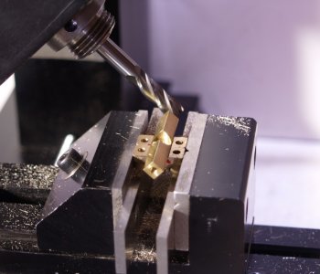
Then the caps. When I checked the caps I found I must have missed a pass when I spot faced for the screws and the bosses were different heights, so I had to square up the mill again to fix that and then reset the angle and the vise. I'm getting good at indicating the vise.
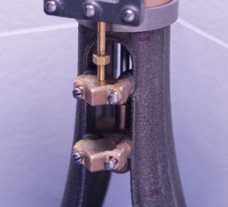
Bearing caps done! The plans call out the thickness of the mounting tabs but not the overall thickness of the cap. Mine are just thick enough to interfere with the eccentric bearing. Rather than trim the point off of the caps I'll make a slightly longer valve slide post.
Then put it all together to see if it works.
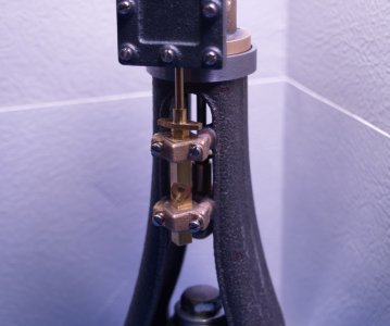
Now I can mark the locations for the screws that hold the cylinder to the frame and get those drilled and tapped (once the tools arrive), and finally remove the frame from its centering fixture.
I feel like I'm on the home stretch.
Eric

I just knew that old drafting triangle would come in handy some day.
After that and moving the vise it was just a matter of cutting the grooves. First the bearings.


Then the caps. When I checked the caps I found I must have missed a pass when I spot faced for the screws and the bosses were different heights, so I had to square up the mill again to fix that and then reset the angle and the vise. I'm getting good at indicating the vise.

Bearing caps done! The plans call out the thickness of the mounting tabs but not the overall thickness of the cap. Mine are just thick enough to interfere with the eccentric bearing. Rather than trim the point off of the caps I'll make a slightly longer valve slide post.
Then put it all together to see if it works.

Now I can mark the locations for the screws that hold the cylinder to the frame and get those drilled and tapped (once the tools arrive), and finally remove the frame from its centering fixture.
I feel like I'm on the home stretch.
Eric
- Joined
- Feb 15, 2020
- Messages
- 375
A little more work today. After taking some measurements to see how far off it came out (not much actually), I removed the frame from the centering fixture and finished the bottom surface parallel to the cylinder mounting flange.
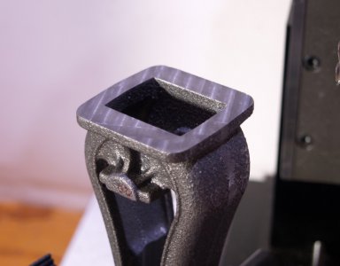
For future reference, if anyone decides to make this kit, this surface is where you want to start! It would have made a lot of decisions much easier. Better late than never I guess.
After that I cleaned up the top of the base to match. I did this before piling up all the stuff on the mill table for the next process. Besides that I had all the hold down clamps out already.
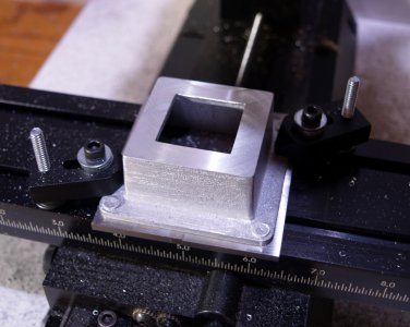
Next I faced the mounting surfaces for the crank shaft bearing caps.
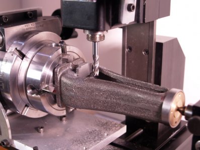
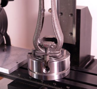
Now it's ready to drill and tap all the remaining holes.
Eric

For future reference, if anyone decides to make this kit, this surface is where you want to start! It would have made a lot of decisions much easier. Better late than never I guess.
After that I cleaned up the top of the base to match. I did this before piling up all the stuff on the mill table for the next process. Besides that I had all the hold down clamps out already.

Next I faced the mounting surfaces for the crank shaft bearing caps.


Now it's ready to drill and tap all the remaining holes.
Eric
Last edited:
- Joined
- Feb 15, 2020
- Messages
- 375
Made a tap extension for the crank shaft bearings.
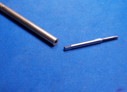
Drilled a hole and filed it to fit.
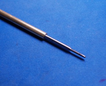
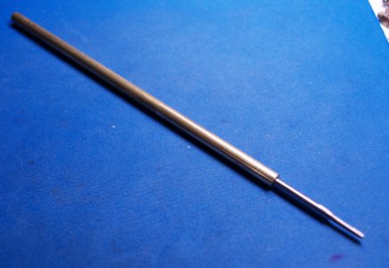
I'll put a cross bar somewhere near the top but I have to leave room so I can hold it loose in a 1/4" mill collet to keep it lined up.
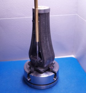
That gives me the clearance I need. I hope it works.
I'll also try making a custom collet for the 6" long #50 drill bit. There isn't enough space between the spindle and table for the frame to stand under a drill chuck. Sherline claims it's 8" but mine measures only 7.5". Either way it's not tall enough. If that doesn't work I have the extended mill column and 2" column spacer coming (soon I hope).
Eric

Drilled a hole and filed it to fit.


I'll put a cross bar somewhere near the top but I have to leave room so I can hold it loose in a 1/4" mill collet to keep it lined up.

That gives me the clearance I need. I hope it works.
I'll also try making a custom collet for the 6" long #50 drill bit. There isn't enough space between the spindle and table for the frame to stand under a drill chuck. Sherline claims it's 8" but mine measures only 7.5". Either way it's not tall enough. If that doesn't work I have the extended mill column and 2" column spacer coming (soon I hope).
Eric
- Joined
- Feb 15, 2020
- Messages
- 375
I saw a post in another part of the forum where someone line bored a part on his lathe carriage and that gave me an idea for boring the crank bearings on my engine. So this is what I've come up with. There is still quite a bit to do before I get to this stage but it's the main problem I've been trying to solve.
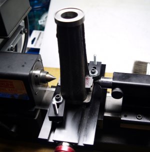
The centers are just there for reference. I'll need to add about 0.044" in shims to bring it up to the spindle center line.
My thoughts are once I get the caps on and finished I can center drill from each side. Then I would use the lathe centers to line the frame casting up and put a pilot hole through each side. I'm thinking that would keep a through drill from wandering too much. Finally I would drill through and ream to size from one direction. That's the "plan" anyway.
Any other suggestions?
Eric
Last edited:
- Joined
- Feb 15, 2020
- Messages
- 375
Still waiting on the mail for my extended column upgrade but I went ahead and drilled the mounting holes for the cylinder in the frame just to see if I could. Setting this up I centered the rotary table to the spindle and locked the X. Then set the frame on that and used a dead center and the inside cylinder head to line it up with the table. Cranked the Y out to remove the center and head and insert the collet and center drill. I squared the frame to the Y using the mounting bosses for the valve slide bearings and an indicator while adjusting the rotary table. I added 45 degrees to the table reading and center drilled the 4 holes 90 degrees apart. That was the easy part. There is less than 1/2" left between the spindle and the top of the frame casting so the center drill is held in a mill collet.
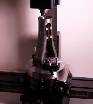
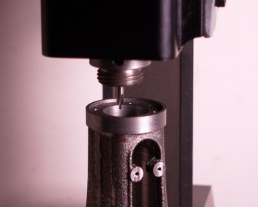
Drilling the holes was more fun. I set the frame on the mill table with two loose hold down clamps. Then put the dead center back in the spindle and used it to line up one of the holes while I tightened the clamps. Raised the spindle, removed the center, and inserted a drill chuck. I had to completely open the chuck jaws to fit the chuck above the frame, insert the drill all the way in and tighten the chuck on the flutes. After drilling through the frame, the drill is removed, then the chuck, loosen the clamps, insert the dead center, line up the next hole and repeat.
Eric
Last edited:
- Joined
- Feb 15, 2020
- Messages
- 375
Still waiting on tools so I went ahead and started on the connecting rod. This is the part that gets to fix the mistakes I made with the crank shaft and the cross head. I cleaned up the sides of the screw bosses on the big end so I had square spots to hold in the vise. Then I faced both ends to just fit their associated parts.
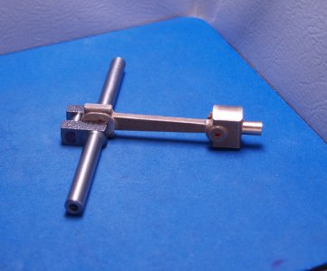
I then drilled the holes for the cap screws so it's ready to tap.
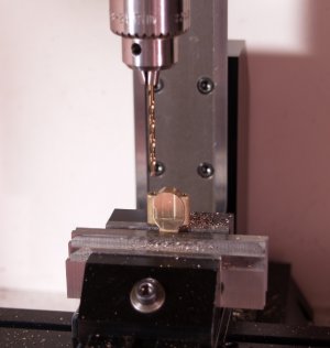
Once the big end is done I'll take a light facing cut on each end to get the clearances in the plans.
The wrist pin hole in the small end is called out in the plan as #42 drill (0.0935"). The hole in the cross head is called out as 3/32" (0.09375"). The nice little stainless steel dowel provided in the kit for the wrist pin is 0.0941" but is listed as 3/32". Am I correct in thinking that I should end up with a slip fit for the pin in the cross head and a press fit in the connecting rod end? That would make sense to me anyway.
Eric

I then drilled the holes for the cap screws so it's ready to tap.

Once the big end is done I'll take a light facing cut on each end to get the clearances in the plans.
The wrist pin hole in the small end is called out in the plan as #42 drill (0.0935"). The hole in the cross head is called out as 3/32" (0.09375"). The nice little stainless steel dowel provided in the kit for the wrist pin is 0.0941" but is listed as 3/32". Am I correct in thinking that I should end up with a slip fit for the pin in the cross head and a press fit in the connecting rod end? That would make sense to me anyway.
Eric
Last edited:
- Joined
- Feb 15, 2020
- Messages
- 375
The taps showed up today so I tapped every hole that needed it. I had 13 at this point.
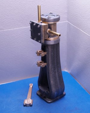
Then I finished the connecting rod. To size the big end you have to saw off the cap and remove about 1/8" from the rod end. Then bolt the cap back on and drill and ream the hole. I was going to use a slitting saw but could not figure a good way to hold the rod secure. My solution was the 4 jaw chuck and the parting tool on the lathe to remove the cap, and then face the rod end to length. My crankshaft journal was undersized and not standard so I couldn't ream the hole in the big end. I don't have the proper measuring tools for holes, so I made a gauge pin the same size as the journal and used the boring head adding 0.001" per pass until the pin just fit the hole.
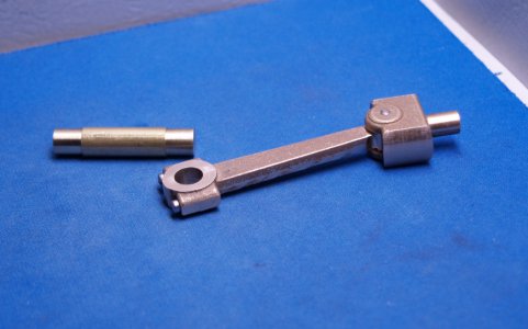
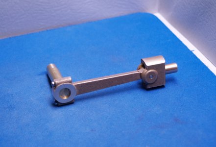
I also increased the sizes of the holes for the wrist pin to get it to fit.
As far as machining goes I'm down to the bottom end bearings, which are probably the most challenging part of this build, the frame mounting holes, and the mounting holes in the base.
Eric

Then I finished the connecting rod. To size the big end you have to saw off the cap and remove about 1/8" from the rod end. Then bolt the cap back on and drill and ream the hole. I was going to use a slitting saw but could not figure a good way to hold the rod secure. My solution was the 4 jaw chuck and the parting tool on the lathe to remove the cap, and then face the rod end to length. My crankshaft journal was undersized and not standard so I couldn't ream the hole in the big end. I don't have the proper measuring tools for holes, so I made a gauge pin the same size as the journal and used the boring head adding 0.001" per pass until the pin just fit the hole.


I also increased the sizes of the holes for the wrist pin to get it to fit.
As far as machining goes I'm down to the bottom end bearings, which are probably the most challenging part of this build, the frame mounting holes, and the mounting holes in the base.
Eric
Last edited:
- Joined
- Feb 15, 2020
- Messages
- 375
Today was Christmas. The Post Office finally decided to deliver my new mill column and spacer block and other bits I ordered from Sherline over a week ago. I also received a "used" indexing attachment from ebay. The price was too good to pass.
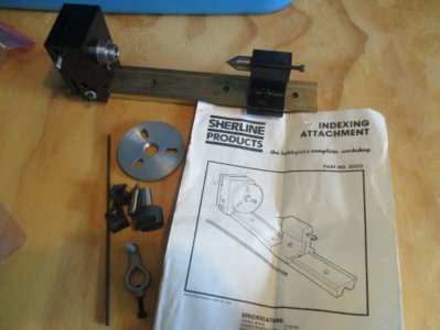
The next task on my engine is the crank bearing caps, but there isn't enough space for the drill chuck with the long #50 drill.
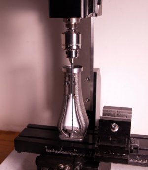
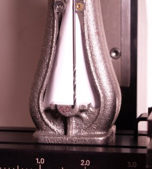
I decided, since the mill is aligned now, to make a 0.070" collet to hold the drill rather than mess with the column or grind the end off the drill.
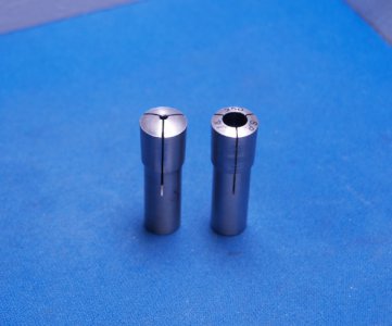
I used the head from the indexing attachment that arrived today and a slitting saw to make the slots. It was an interesting little exercise. Hope it works!
Eric

The next task on my engine is the crank bearing caps, but there isn't enough space for the drill chuck with the long #50 drill.


I decided, since the mill is aligned now, to make a 0.070" collet to hold the drill rather than mess with the column or grind the end off the drill.

I used the head from the indexing attachment that arrived today and a slitting saw to make the slots. It was an interesting little exercise. Hope it works!
Eric
- Joined
- Feb 15, 2020
- Messages
- 375
The collet I made worked like a champ! Drilling an tapping the holes went smooth and easy. Very different from when the tap broke earlier.
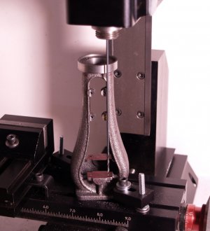
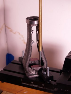
Didn't need any extra leverage for the tap. It went in all 4 holes with just finger pressure on the extension I made. The 4 bosses for the valve slide bearings are obviously harder than the rest of the casting.
After mounting the caps I faced the outer surfaces square with the rest of the frame.
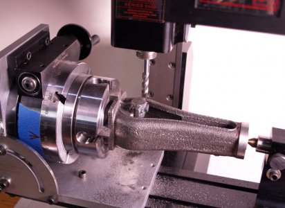
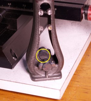
One thing Sherline doesn't tell in their instructions is their adjustable tail stock can force a rotary table setup like this out of alignment with very little pressure. So put an indicator on your part when setting up to make sure it doesn't move on you.
I still need to face the insides before boring them.
Eric


Didn't need any extra leverage for the tap. It went in all 4 holes with just finger pressure on the extension I made. The 4 bosses for the valve slide bearings are obviously harder than the rest of the casting.
After mounting the caps I faced the outer surfaces square with the rest of the frame.

One thing Sherline doesn't tell in their instructions is their adjustable tail stock can force a rotary table setup like this out of alignment with very little pressure. So put an indicator on your part when setting up to make sure it doesn't move on you.
I still need to face the insides before boring them.

Eric
Last edited:


