Themac Tool Post Grinder DIY Spindle

Yorkus

Registered
Registered
Joined
Dec 11, 2014
Messages
31
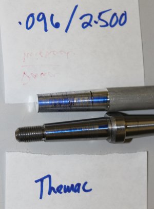
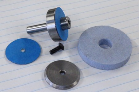
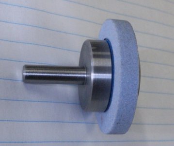
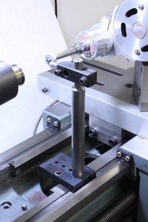
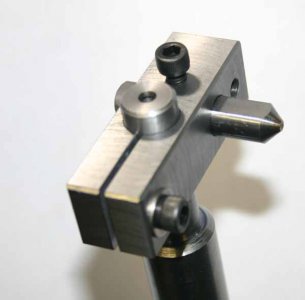
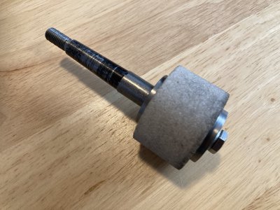
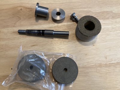
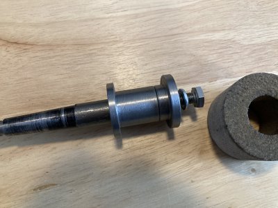
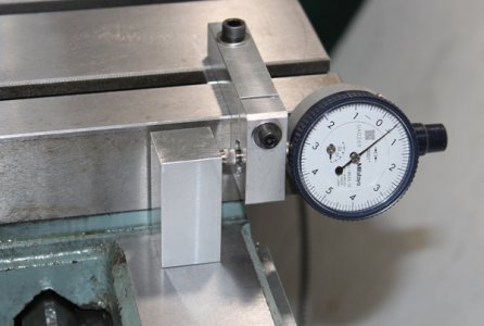
I have recently acquired a Themac J45 TPG. Unfortunately it didn't come with any of the accessories, such as spindle extension & different sized pulleys to vary the spindle speed. I am confident I can make the pulley's but I think the spindle extensions will be a little more involved. I guess at this point I am wondering if anyone else has done this & any advice you could offer. I have started by measuring the spindle bore taper to get a plan on how to proceed.
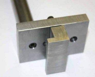
It appears to be 7/8" per foot taper or very close to that. The Thread in the spindle appears to be 5/16"-24. If anyone has better information or a drawing that would be great.
And before anyone mentions it I know Themac is still in business and selling parts & accessories. The problem is this is just a hobby for me and I can't begin to justify buying new at the prices I was quoted. These machines are priced at almost $3000 new and to buy a single spindle extension is over $200.

Thank You ahead of time for any help and/or advice!

York
 
Hi Yorkus. Sorry I didn't see your post until just now. Did you already make your parts? I have fiddled with making custom Themac arbors (J35). Their taper is their own recipe (from the horses mouth). I can dig up my notes if still of interest.
 
Hi Petertha

Thank you for the reply. I understand you not seeing my post for a while if at all since it is not the most common subject.
It's been a while since I did anything with the tool post grinder, it ended up going on the back burner for a while.

Before putting it all aside I measured the Spindle Taper and came up with 0.0353" per inch of taper. As I understand it, this is about 2 degrees.
Shortly after that I made a short spindle and it seem to fit well. I am needing to make some more spindles for different size grinding wheels.
Now that winter temperatures have set in I'm not as quick to go out to the unheated shop.

I am very interested in your knowledge on the subject if you don't mind sending your findings and any possible experience in making spindles.
 
Sorry for the delay. I found my drawing of an ID grinder arbor that I made, but looks like I didn't take a picture of it yet. My drawing shows the taper angle I settled on after measuring a few Themac arbors I have & basically taking the average. I then made a few taper test slugs without the thread end & checked the fit by slight twist & Jiffy marker rub off. They seem to fit as snug as the stock ones.

Hopefully this isn't too convoluted. At the time I wanted an known, documented angle reference that I could set up anytime I wanted to make another arbor. For the test tapers I set my compound angle by using a parallel bar extending from the spindle, mini sine bar & appropriate spacer. But for the arbor I made I held a Themac arbors in my collet chuck & adjusted the compound angle by running DTI down the surface (exactly centered of course). When I measured my resultant taper it seemed to correspond to the drawing & test slugs so I think its close.

The other thing I learned is the 5/16-24 thread that I cut according to the book (class 2A, OD & pitch diameter) fit too tight in spindle thread. I then measured the OD & PD of my Themac arbors & they are on what would be considered on the loose side. So I don't know what to say about that other than check it beforehand or cut a thread & check that independently. I'll try & round up some more info from my notes,
 

Attachments

  • arbor-1.PDF
    75.7 KB · Views: 18
  • IMG_3384_edited-1.jpg
    IMG_3384_edited-1.jpg
    300.3 KB · Views: 31
I just re-read your post. You referenced 7/8" per foot, so that's 0.0729 in/in. My drawing shows .0391 in/in equivalent of the taper angle, times 2 for included angle = 0.0782 in/in equivalent. Very close. Themac never disclosed their value when I chatted them a while back, they said they have had the same turning/grinding setup for long, long time. Maybe you have the recipe.
 
Small wheels are hard to find in my neck of the woods. I had these cut by a water jet guy from 1/4" commercial wheel. Working good so far. I wear a shield just in case.
 

Attachments

  • IMG_2823_edited-1.jpg
    IMG_2823_edited-1.jpg
    196.4 KB · Views: 25
  • IMG_2825_edited-1.jpg
    IMG_2825_edited-1.jpg
    224.5 KB · Views: 22
  • IMG_5539_edited-1.jpg
    IMG_5539_edited-1.jpg
    35.6 KB · Views: 25
My self made wheel dressing tool
 

Attachments

  • IMG_2645_edited-1.jpg
    IMG_2645_edited-1.jpg
    203.6 KB · Views: 25
  • IMG_5703_edited-1.jpg
    IMG_5703_edited-1.jpg
    32.9 KB · Views: 24
  • IMG_5704_edited-1.jpg
    IMG_5704_edited-1.jpg
    27.3 KB · Views: 26
When I measured the arbor taper I used the following method:
I removed the arbor from the THEMAC motor and removed the Pulley from the drive end.
I then put the drive end of the grinder spindle in a collet in the lathe and supported the other end with a steady rest.
Using 2 DTI's I arranged one as a travel dial to measure the 1" of travel. The second DTI was used with a Brown & sharp bore attachment to measure the taper. What I came up with after averaging repeated measurements Into & then out of the spindle, was 0.0354" taper per 1.00".
My original post stating the taper was 7/8" included was before I had a chance to measure accurately.

For the threaded end if I recall I single point threaded it most of the way and then ran a tap over it to finish the treads.
Seems to fit quite well.

I have attached photos of the one arbor I have made so far. On my second attempt the material I used was case hardened and I had a hell of a time with my lathe getting through the case to the softer material in the middle and ended up with a bad taper. When I get back into this I am going to ether use different material or anneal it before starting. As you can see the surface finish is not the best and the "rub" test shows an "OK" contact area.

Part of the reason this project went on the back burner was because I sold my Atlas Commercial 12x36 Lathe and Purchased a Taiwan Import 12 x 36 gearhead. Looking forward to getting some more time on this Lathe to compare to the Atlas.
 

Attachments

  • IMG_1265.jpg
    IMG_1265.jpg
    2.5 MB · Views: 21
  • IMG_1263.jpg
    IMG_1263.jpg
    2.7 MB · Views: 18
  • IMG_1264.jpg
    IMG_1264.jpg
    2.3 MB · Views: 18
Last edited:
I really like all the parts you have made for yours.
I will need a way to hold the diamond nib to dress the wheel. I like what you came up with.
As for the wheels I stopped into a local grinding Company to see what they may have for sale.
He gave me the wheel that I made the arbor for, OD 1.750", ID .75", Width of 1.00"

Since then I found the package you see in the photos of the wheels from Ebay.
There are a number of option on ebay so maybe try that if you find you need more.
 
Tour parts look good. Goes without saying hopefully to cover up your lathe bed when grinding as especially dressing the wheel insitu. I put a vaccum nozzle on when I do this.

Somewhat related, I think I posted this elsewhere but here is what I came up with to accurately measure in-feed when using TPG. Its my tenths reading mini dial gauge, held by a clamp via the stem, an aluminum stop block with some neodium magnets glued in so it can be quickly positioned & attached to the cross slide base. The clamp is bolted to the table moving surface via nuts in the T-slot. I find once the TPG is running, the dials become a bit lively, probably due to some micro vibration transferring through the compound. This is kind of a direct reading, finer resolution method. It also picks up the teeniest variations of locking the table.

I think TPG's definitely have their place. But my big issue with them is they are nearly, if not totally impossible to position to the work when the end of the part needs to be supported with a tailstock center. The spindle or extending motor assembly is always trying to occupy the same real estate as the tailstock casting/quill.
 

Attachments

  • IMG_3392_edited-1.jpg
    IMG_3392_edited-1.jpg
    141 KB · Views: 14
  • IMG_3393_edited-1.jpg
    IMG_3393_edited-1.jpg
    147.8 KB · Views: 17
  • IMG_3396_edited-1.jpg
    IMG_3396_edited-1.jpg
    197 KB · Views: 19
Back
Top