- Joined
- Jun 15, 2018
- Messages
- 294
The thing is that this power supply would be far easier to do using switching PSU technique. However, there are these boat-anchors and as it happened those suit for the task. This power supply is going to be used to feed an induction heater. There is a project thread for that and I will give a more detailed description there ... later.
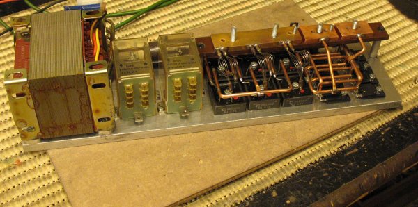
Auxiliary transformer, soft start relays (25A continuous, 100A rush), rectifier (90A continuous), FET array for power control (240A continuous). The wiring is NOT an overkill, I am actually a little bit worried about it. Time will tell.

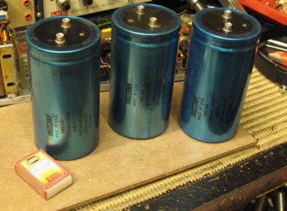
Some smoothing capacitors are required. These are high current capacitors 30mF (aka 30000uF) a pop. Although these are quite old they still exceed their specifications. They have very low ESR (Effective Series Resistance) and their capacitance is still 10% over what is on the label. The leakage current @50V was 4mA.

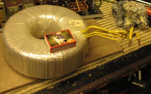
This is why a soft start is required. The toroid transformer is fully capable of frying the fuse if connected to mains without precautions. The soft start relays first connect a 100 ohm resistors and then after the voltage in the capacitors is at working level this resistor is bypassed by the other relay. This transformer can output 36V @ 50A. It is also quite heavy.

Auxiliary transformer, soft start relays (25A continuous, 100A rush), rectifier (90A continuous), FET array for power control (240A continuous). The wiring is NOT an overkill, I am actually a little bit worried about it. Time will tell.

Some smoothing capacitors are required. These are high current capacitors 30mF (aka 30000uF) a pop. Although these are quite old they still exceed their specifications. They have very low ESR (Effective Series Resistance) and their capacitance is still 10% over what is on the label. The leakage current @50V was 4mA.

This is why a soft start is required. The toroid transformer is fully capable of frying the fuse if connected to mains without precautions. The soft start relays first connect a 100 ohm resistors and then after the voltage in the capacitors is at working level this resistor is bypassed by the other relay. This transformer can output 36V @ 50A. It is also quite heavy.


