Threading at 400 RPM

For those that have an interest in constructing the clutch for a G0602 the best source of detailed drawings is from the magazine. The reason being that the editor George Buliss expends considerable effort to model them in SolidWorks. This not only produces better drawings than I can produce it also produces exploded views and checks for dimension conflicts. Buying a back issue of the article or taking advantage of their special $19.95 offer are two ways to obtain excellent drawings. My drawings are done using SketchUp which has limitations.

This is a very long article with many photos and drawings which presents problems when trying to publish it in a forum. I have not planned to publish it online because of its size. If there is enough interest in the project I will take another look attempting to do that.

Thank you for the kind feedback.

Jim
 
Looks great I like the clutch
I have found I can thread at high speed if the threads are the same as the lathe lead screw or any multiple 2X 3x 4X. or with my lathe 8 tpi 16 tpi 24 tpi 32 tpi. FYI doing this will need some free space at end of thread for stoping

Dave


For those that have an interest in constructing the clutch for a G0602 the best source of detailed drawings is from the magazine. The reason being that the editor George Buliss expends considerable effort to model them in SolidWorks. This not only produces better drawings than I can produce it also produces exploded views and checks for dimension conflicts. Buying a back issue of the article or taking advantage of their special $19.95 offer are two ways to obtain excellent drawings. My drawings are done using SketchUp which has limitations.

This is a very long article with many photos and drawings which presents problems when trying to publish it in a forum. I have not planned to publish it online because of its size. If there is enough interest in the project I will take another look attempting to do that.

Thank you for the kind feedback.

Jim

Thanks for the reply. I have only gone through the article a couple of times so far and just made a stab at getting the tooling. I will transfer the published drawings to cad before I do any cutting. I don't like to have originals out in the shop. They collect guck way too fast. Cutting oil does a pretty good job of dissolving ink, too. Its nice to have a way to replace damaged or evaporated drawings quickly.

Larry
 
A bit of info from Grahams site.

http://modelengineeringwebsite.com/Meek_screwcutting_clutch.html

Metric I'm afraid :whiteflag:

I've been checking out the drawings at this site. I don't find them to be particularly helpful. There are lots of parts, shafts that seem to fit inside of other shafts, collars, bushings, etc. By the time I got to sheet 12 and I see how it is supposed to all fit together, I'm completely lost!:noidea: :whiteflag:

I have signed up for a free trial offer of the Home Shop Machinist, so I'm hoping the drawings that Jim and George have put together are easy enough for a tenderfoot such as myself to figure out. . . . Really the idea is a big help as it is. I have a really old Leblond, so I'll need to reverse-engineer everything to work with it anyway. . . .

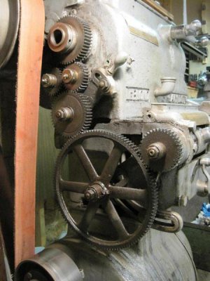
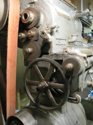
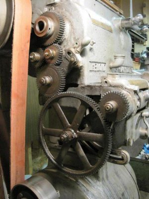
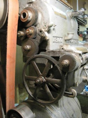
Here's a pic of the gear-train between the spindle and the QCGB

IMG_4911_zps20817d8a.jpg

Oh, and guess what? I'm pretty sure that big gear is 121 tooth, so no easy conversion to metric. . . .

Jim

IMG_4911_zps20817d8a.jpg

IMG_4911_zps20817d8a.jpg

IMG_4911_zps20817d8a.jpg
 
Can't you get the Home Shop Machinist at the book store, I thought Barnes & Knoble carried it?
 
Hello Jim2, thanks for the picture of the Leblond. You have an interesting gear train. The good news is that it appears you have plenty of room. Is the top gear in the train your spindle gear? You can use the real estate currently occupied by the reverse tumbler gears since you will no longer need them.

Don't be intimidated by the number of shafts, gears and collars. It is one of those concepts that at first appears confusing but as you work your way through it the light goes on and the simplicity of the method become clear. The exploded view that George placed in the article is excellent and gives a good over view of how the pieces fit together. Just remember that the two steel dog gears are always rotating in opposite directions and the position of the dog disc (to the left or to the right) will control which of the two dog gears controls the direction of the output gear.

Another point of interest and one that Gray points out in his writings is that the pressure on these gears is actually quite low. This is one of the reasons that this device functions so well and can be shifted from forward to reverse while running at speed (300-500 rpm).

Dave raised the question of stopping when the end of the thread is reached. The measurements that I have taken show that stopping is surprisingly consistent ranging in the 0.002-0.006" range. I routinely thread into blind holes at speed. The setup process is easy and gives you the opportunity to test and adjust the ranges. I have a fine adjust on both the forward and reverse trip stops. I have DRO's on my lathe and I can adjust the distance of the threading into the hole using the DRO without having the tool inserted into the hole. Once I am satisfied I make a run or two with the threading bit in place. For internal threads I always thread the far wall with the threading insert inverted. This allows me to retract the tool at the end of the run just as I do for external threads. It is one of those things that once you do it a few times you wonder why you ever used a different process.

Jim
 
Yes, the top gear is fixed to the spindle on the Leblond. And, yes oceans of space to create this clutch! Too much space maybe--There will probably be a need for some additional idler gears somewhere in there.

I think I do understand the "big picture" of what this modification does for threading and even pretty much how it works. It's the details in those drawings that have me scratching my head. For instance the actual mechanism by which the lever transfers its motion to the dog clutch is not at all clear to me. I can't make out any eccentric, lever, or other mechanism that connects the hand-lever to the clutch! I know there is one, but??? I'm guessing that some of the details can be implemented any number of different ways, and that your implementation may even be different in this regard. Like I said earlier, I'm looking forward to seeing the article in Home Shop Machinist.

Another example of my confusion is that the stud that the reverser gears run on seem to have a large radial hole in it that the shaft for the hand-lever goes through! It's not clear to me why it's done that way. I'm guessing that it's not important to the design, but rather was a design choice that was made to keep things compact. . . . Yet??? And, again another implementation could be totally different.:pondering:

I have been jones-ing for metric threading for some time now. The old Leblond is in suprisingly good shape for its age. I has an interesting range of features including QCGB, taper attachment, separate feed rod and threading leadscrew, clutch on the spindle, etc. Even though it's top speed doesn't compare to modern offerings, it's variety of low speed settings, variety of work-holding, etc. make up for it--well at least in my mind! That's a rather long way of saying that I'm not willing to give it up just for lack of metric threading. OTOH, it does have a threaded spindle, which prevents me from employing a common method that others use to perform metric threading (stopping spindle, reversing to the beginning of the thread, stopping spindle, doing another pass, etc.).

That's where this dog-clutch comes in! The spindle is never reversed; therefore, no issues with the attachment of my chuck to a threaded spindle.

You mentioned that the stress on the clutch is quite low. I've been thinking about that too. When the dog clutch is reversed, the gear train would have as much as 300+ degrees of rotation to coast to a stop before the pin reaches the end of the slot and starts driving in the other direction. Even then the backlash between all the gears in the train will be taken up incrementally before the whole train is fully reversed and driving in the opposite direction. Like you said--not that much stress at all!

Going a bit further off the track--I mentioned that the big gear is 121 tooth in my last post. I'm not 100% sure of that. I counted again and got 120 teeth. Lighting is poor, it's difficult not to lose track w/ all those teeth, etc. The thing is, I'm pretty sure that it doesn't matter. With the 10DP gears that I've got, a 127 tooth gear would be 12.9" in diameter. Even if I could source a gear blank of this size, I couldn't cut the teeth--mind you I haven't actually made any other gear yet, either. It's just that doing work on the scale of 127 teeth on a 13" gear blank is quite different than doing a 47 tooth gear (4.9" diameter gear blank), which would be utilized for a set of 47/37 tooth metric conversion gears!

Thanks for doing the legwork on this project and blazing a trail for folks like me to follow!

Jim
 
For internal threads I always thread the far wall with the threading insert inverted. This allows me to retract the tool at the end of the run just as I do for external threads. It is one of those things that once you do it a few times you wonder why you ever used a different process.

Jim

I haven't use that method in the past. Most of the threading I do is external anyway, but I have done internal threads enough to understand some of the issues. In order to thread against the "near wall" w/ the tool facing upward, one should change the angle of the compound so that the tool isn't contributing to the backlash. This means positioning the compound to the left of the cross-slide, which is awkward, and at times dangerous, as that places the compound very close to the chuck. Or, the compound can be turned 180 degrees from there with it facing towards the operator, and the handle behind the axis of the lathe spindle. The tailstock can easily interfere in this position and it is even more awkward than the other position.

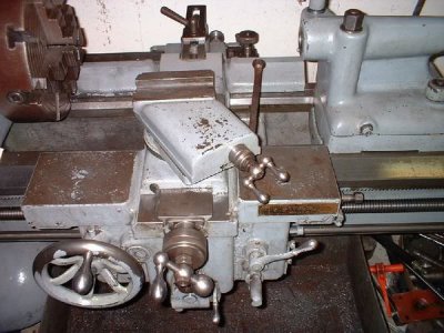
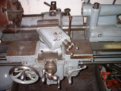
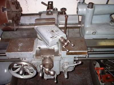
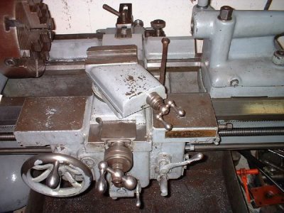
Here's a pic of the compound on my lathe:

26-Saddle.jpg

With the way the compound has the 30 degrees built into it, changing the angle is even more awkward!

Add to that, sometimes things can get a little hectic when I'm threading, and I'm not always in the best frame of mind. I know I've accidentally jammed the tool into the work at the end the pass thinking that I was withdrawing the tool from the cut. This is no doubt due in part to muscle-memory taking over from having done much more external threading than internal threading. . . .

Yeah, threading against the far wall with an inverted tool seems like a pretty good idea!

The only down-side that I can think of is that the travel on my cross-slide is somewhat limited. I can see where threading a *really* large hole might mean that I wouldn't have enough travel to hit the far wall. That doesn't seem all that likely for most work, though.

Jim

26-Saddle.jpg

26-Saddle.jpg

26-Saddle.jpg
 
Jim2 you certainly have an interesting piece of equipment. They don't make them like that any more, substantial is a word that comes to mind. Modifying the old Leblond would be a real interesting project.

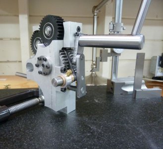
I reviewed the article and I believe I see where the confusion over how the mechanism works originates from. I originally wrote this to be a a single issue article but due to the length they had to split into two segments. The second segment will cover the linkages and the mechanisms to disengage the clutch etc. What is not shown in the current issue is the shifting fork that engages the dog clutch disc. If you look at the exploded diagram (Figure 2, item #8) you will see the groove that is turned into the disc, a shifting fork fits into that groove and moves the disc to the left or right. Looking at photo 12 you can see the gap between the reverse and forward idler gears. The dog clutch disc is keyed to the outer shaft that rotates on the inner shaft which is fixed to the housing. Looking at photo 12 the nearest gear is the output gear and it is also keyed to the outer shaft thus as the dog clutch disc is moved to engage either the forward or reverse gear this output shaft will rotate in that direction and that motion is coupled to the output gear and the rest of the gear train.

Photo 16 Assembly with fork and shift rod.jpg
This photo shows the completed clutch assembly and shows the shifting mechanism that is linked to the control handle. The rod exiting the rear attaches to the carriage trip rod and disengages the clutch when a predetermined point is reached either on the forward or reverse travel direction.

Since you have a taper attachment you must have a means to disengage the cross feed screw which brings to mind the ability to add a cross slide retractor. The retractor is a huge improvement for threading, it eliminates the confusion that sometimes pops up when you are trying to remember what the in-feed setting was. It can be used on both external and internal threads, very handy item.

I tried to count the number of teeth on your large gear but I lost count when I got into the darker spots around #80 or so. You can get very close on metric threads. On the G0602 I determined the exact gear ratio for every position on QCGB and using all of the various external gears. I plotted that on a spreadsheet in both inches and mm's. For most threading applications the amount of thread actually engaged is small and thus with a close match in Imperial terms and a slightly looser fit you can satisfy most needs. The G0602 has an Imperial lead-screw (12 TPI) so some metric threads are an approximation even using the 127/120 ganged gear input to the QCGB.

The G0602 also has a threaded spindle for chuck attachment etc. I have converted my lathe to a variable speed and as part of the speed control I use soft-start/stop to ensure that the spinning mass stays put.

Jim

Photo 16 Assembly with fork and shift rod.jpg
 
Back
Top