

-
Welcome back Guest! Did you know you can mentor other members here at H-M? If not, please check out our Relaunch of Hobby Machinist Mentoring Program!
You are using an out of date browser. It may not display this or other websites correctly.
You should upgrade or use an alternative browser.
You should upgrade or use an alternative browser.
Threading on a PM1127 lathe - turning instead of threading
- Thread starter Pcmaker
- Start date
- Joined
- Nov 27, 2012
- Messages
- 7,852
I don't undertand why none of this is in the manual
The manual that usually comes with an asian import machine is a basic generic manual from the CM. Distributors like PM & Grizzly rewrite the manual. Use the PM manual & forget the CM's manual.
- Joined
- Apr 30, 2015
- Messages
- 11,251
I guess the reasoning is if you are capable enough to use machine tools then you can figure things out without detailed manuals. Also, it's a fact that people generally don't read manuals anyway. Cost probably is a factor too
Not making excuses for poorly written manuals, just sayin'
Not making excuses for poorly written manuals, just sayin'
Last edited:
- Joined
- Jun 12, 2018
- Messages
- 712
I just tried it. I was trying to do 1.25mm but the gears don't seem right. Used a spacer for "H"
Also, the inserts are such a pain to get out and put on.
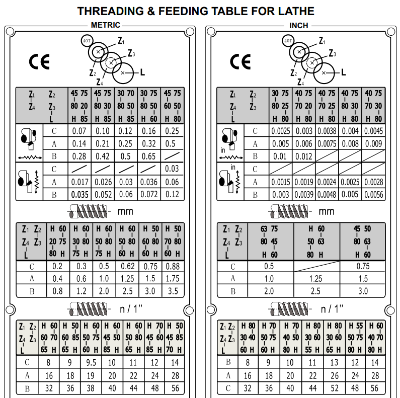
Anyone know what the picture means on the top of the threading chart? And why are there metric and inches sections under both metric and inches?
Also, the inserts are such a pain to get out and put on.
Anyone know what the picture means on the top of the threading chart? And why are there metric and inches sections under both metric and inches?
Last edited:
- Joined
- Jun 12, 2018
- Messages
- 712
I got this email reply:
Hello,
The H is a spacer, thats it.
Look at how the numbers are shown in the thread chart picture, (not
the Z, ignore that, just use the gear teeth numbers) They are set up
exactly how they should go, looking at it from the front. The top gear
mates with the spindle and then they go from there. Put them exactly as
the numbers are in each chart

- Joined
- Nov 27, 2012
- Messages
- 7,852
Those lines indicate which gears mesh (drive) together. If you look at the rest of the chart it's consistent as well as the spacer & gear position for the leadscrew, all except the ones I pointed out.
- Joined
- Nov 27, 2012
- Messages
- 7,852
I just tried it. I was trying to do 1.25mm but the gears don't seem right. Used a spacer for "H"
Also, the inserts are such a pain to get out and put on.
Anyone know what the picture means on the top of the threading chart? And why are there metric and inches sections under both metric and inches?
Ok, since it seems you are still having trouble getting 1.25mm pitch I'll take a stab at it.

Edit: See next post.
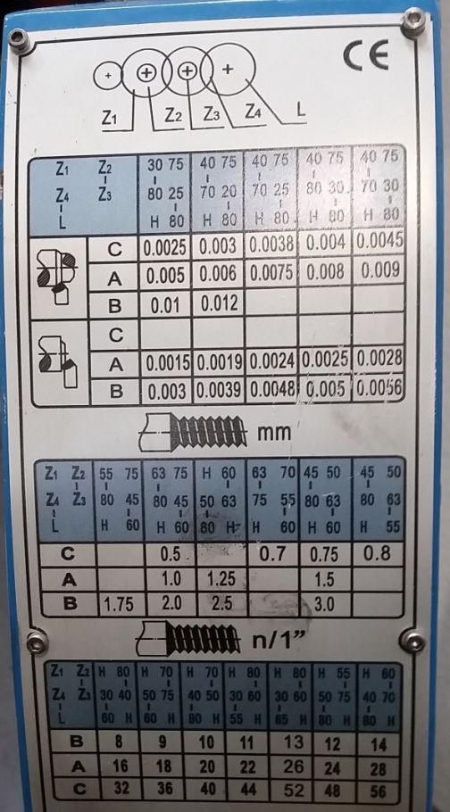
Looking at the 2 diagrams I circled in blue, to get 1.25mm pitch.....
40T is at the very top which I assume is a gear off the spindle that can not be changed.
Standing in front of the lathe looking at the change gears, Z1 & Z2, 60T would be on the inside (right side closest to the headstock) & a spacer would be on the outside (left side).
Z4 & Z3, 80T would be on the inside & 50T would be on the outside. There's a line inbetween Z2 & Z3 so that would mean the 60T & 80T gears mesh together.
Finally for the leadscrew drive, another spacer used on the inside & another 60T gear on the outside that would mesh with Z4 which would be the 50T gear.
Lever on position A.
However what doesn't make sense to me is on the right side of the chart it shows a different gear setup for 1.25 also using position A. So if the above gear combo doesn't give you a 1.25mm pitch, then try the following configuration.
