Timmeh's Workshop.

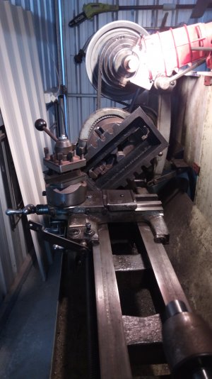
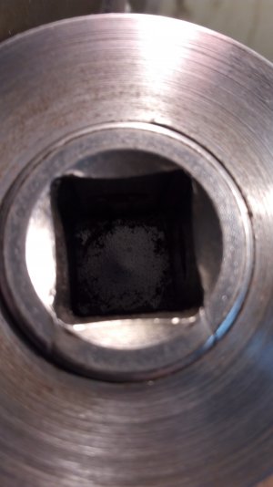
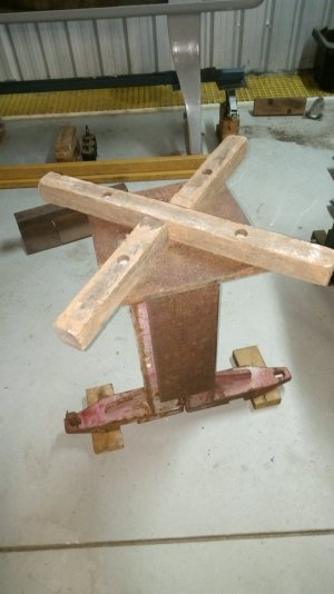
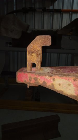
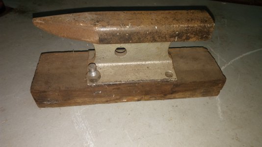
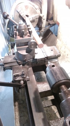
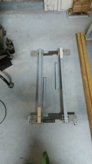
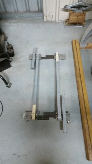
It swings... Some kind of keeper through the spindle, that will be the base sorted.
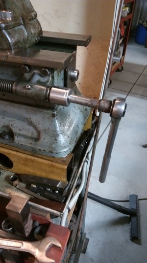
As good as it can be, not today as a lot of measurin' an' checkin' an' refinin' the setup gotta happen first.
Will post another of this when it gets done.
 

Attachments

  • IMG_20210804_110942.jpg
    IMG_20210804_110942.jpg
    3.1 MB · Views: 38
  • IMG_20210804_111006.jpg
    IMG_20210804_111006.jpg
    2.7 MB · Views: 37
  • IMG_20210804_111133.jpg
    IMG_20210804_111133.jpg
    2.6 MB · Views: 33
Fix for a socket extension that split at the ratchet end.
Bit of turning, boring, pressing, milling and linishing.
 

Attachments

  • IMG_20210806_111152.jpg
    IMG_20210806_111152.jpg
    2.9 MB · Views: 31
  • IMG_20210806_111217.jpg
    IMG_20210806_111217.jpg
    3 MB · Views: 30
  • IMG_20210806_114527.jpg
    IMG_20210806_114527.jpg
    3.2 MB · Views: 27
  • IMG_20210806_114604.jpg
    IMG_20210806_114604.jpg
    3.2 MB · Views: 26
  • IMG_20210806_114657.jpg
    IMG_20210806_114657.jpg
    2.8 MB · Views: 27
  • IMG_20210806_114822.jpg
    IMG_20210806_114822.jpg
    2.4 MB · Views: 32
Another project that's been on hold for some time, due to lack of time, suitable material or just plain engineers block.
Now nearing completion of phase lV (or is it V.... not sure)
of development.
Still needs modification for more width capacity, perhaps even a bit shorter length way's, works as intended.
Makes moving machines bit easier.
Bought the castor's and "U" bolts, the rest is scrounged material.
Ready to set the "IXL Leader" on the old screw jacks from the atlas.
 

Attachments

  • IMG_20210809_092547.jpg
    IMG_20210809_092547.jpg
    2.8 MB · Views: 25
  • IMG_20210809_092657.jpg
    IMG_20210809_092657.jpg
    2.6 MB · Views: 26
  • IMG_20210809_094308.jpg
    IMG_20210809_094308.jpg
    3 MB · Views: 28
  • IMG_20210809_102204.jpg
    IMG_20210809_102204.jpg
    3 MB · Views: 23
  • IMG_20210809_102632.jpg
    IMG_20210809_102632.jpg
    2.6 MB · Views: 21
  • IMG_20210809_103046.jpg
    IMG_20210809_103046.jpg
    2.8 MB · Views: 22
  • IMG_20210809_104454.jpg
    IMG_20210809_104454.jpg
    2.9 MB · Views: 22
  • IMG_20210809_105435.jpg
    IMG_20210809_105435.jpg
    2.7 MB · Views: 22
  • IMG_20210809_105839.jpg
    IMG_20210809_105839.jpg
    2.9 MB · Views: 22
  • IMG_20210809_114743.jpg
    IMG_20210809_114743.jpg
    2.8 MB · Views: 28
Tim,

Those adjustable wheels look very useful.

Also, very interesting anvil:
1628511739905.png

I'm betting it was welded out of plate.
That wide slot seems to have a dovetail on one side.
Is that for a special purpose or was it already in the plate?

Thanks,
-brino
 
Tim,

Those adjustable wheels look very useful.

Also, very interesting anvil:
View attachment 374804

I'm betting it was welded out of plate.
That wide slot seems to have a dovetail on one side.
Is that for a special purpose or was it already in the plate?

Thanks,
-brino
I scrounged the remnants of an old automotive chassis straightener. Used two of what you see there, bolted together with a piece of 5mm plate between them and slotted onto a short section of I beam.
I'll get a few pics sometime soon.
 
All scrounged material(steel, wood, nuts/bolts and the hammers.
Bar the "finished" train rail anvil, that was my grandfather's. Oxy cut to shape and roughly dressed with an angle grinder.
Rough and ready, still a work in progress.
 

Attachments

  • IMG_20210810_072111.jpg
    IMG_20210810_072111.jpg
    2.9 MB · Views: 20
  • IMG_20210810_072638.jpg
    IMG_20210810_072638.jpg
    3.3 MB · Views: 19
  • IMG_20210810_072356.jpg
    IMG_20210810_072356.jpg
    2.4 MB · Views: 17
  • IMG_20210810_072424.jpg
    IMG_20210810_072424.jpg
    2.8 MB · Views: 16
  • IMG_20210810_072909.jpg
    IMG_20210810_072909.jpg
    3 MB · Views: 18
  • IMG_20210810_072947.jpg
    IMG_20210810_072947.jpg
    2.2 MB · Views: 18
  • IMG_20210810_073013.jpg
    IMG_20210810_073013.jpg
    4.2 MB · Views: 17
  • IMG_20210810_073033.jpg
    IMG_20210810_073033.jpg
    3.9 MB · Views: 15
  • IMG_20210810_073050.jpg
    IMG_20210810_073050.jpg
    3.7 MB · Views: 15
  • IMG_20210810_073200.jpg
    IMG_20210810_073200.jpg
    2.4 MB · Views: 15
  • IMG_20210810_073259.jpg
    IMG_20210810_073259.jpg
    3.2 MB · Views: 15
  • IMG_20210810_073703.jpg
    IMG_20210810_073703.jpg
    2.7 MB · Views: 15
  • IMG_20210810_073547.jpg
    IMG_20210810_073547.jpg
    3.5 MB · Views: 14
  • IMG_20210810_074024.jpg
    IMG_20210810_074024.jpg
    2.9 MB · Views: 20
I was struck with a brainwave (likely turn out to be a brainfart) while doing the socket extension, set me to pondering about how far I could go with "thread pitch".
Driving via the leadscrew, using die grinder to cut a helical pattern.
Up to 1 11/16" pitch now using extra change gears (I have near full sets in metal and plastic) without modifying the existing spindle gear setup.
Next step is to split the 116 tooth "ring gear" to make a custom spindle gear that replaces the 32 tooth spindle and compound stud gear.
Similar to the one I did for the leadscrew(last pic).
 

Attachments

  • IMG_20210812_201823.jpg
    IMG_20210812_201823.jpg
    3.1 MB · Views: 14
  • IMG_20210812_201909.jpg
    IMG_20210812_201909.jpg
    3 MB · Views: 12
  • IMG_20210812_201957.jpg
    IMG_20210812_201957.jpg
    2.9 MB · Views: 11
  • IMG_20210812_203315.jpg
    IMG_20210812_203315.jpg
    3.1 MB · Views: 11
  • IMG_20210812_203325.jpg
    IMG_20210812_203325.jpg
    3.9 MB · Views: 18
Needed a counterweight while turning the diameter, to stop tool digging in due to vibration/high back rake/wear in cross feed screw+nut.
Indexing needs a little refinement, but hey, we're still in R + D yet.
3 start, indexing by setting a dial indicator, release half nut and move carriage x number of threads, reengage half nut.
Now to do reverse direction, should make a GROOVY file handle.
Don't forget, not under power. Driving by hand via the leadscrew.
 

Attachments

  • IMG_20210814_170443.jpg
    IMG_20210814_170443.jpg
    2.7 MB · Views: 18
  • IMG_20210814_190911.jpg
    IMG_20210814_190911.jpg
    2.9 MB · Views: 18
  • IMG_20210814_190929.jpg
    IMG_20210814_190929.jpg
    2.6 MB · Views: 16
  • IMG_20210814_191007.jpg
    IMG_20210814_191007.jpg
    2.7 MB · Views: 16
  • IMG_20210814_204049.jpg
    IMG_20210814_204049.jpg
    2.8 MB · Views: 13
  • IMG_20210814_204012.jpg
    IMG_20210814_204012.jpg
    3.2 MB · Views: 13
  • IMG_20210814_203946.jpg
    IMG_20210814_203946.jpg
    2.7 MB · Views: 15
Last edited:
Bit more progress on the machine skate/trolley thingamabob.
Three sets of "legs" to improve adjustabilityness from a tad bigger than I need down to roolly roolly smol.
Now to drill a few more holes.
 

Attachments

  • IMG_20210816_193800.jpg
    IMG_20210816_193800.jpg
    2.5 MB · Views: 7
  • IMG_20210816_193837.jpg
    IMG_20210816_193837.jpg
    2.4 MB · Views: 7
  • IMG_20210816_193922.jpg
    IMG_20210816_193922.jpg
    2.4 MB · Views: 7
  • IMG_20210816_194041.jpg
    IMG_20210816_194041.jpg
    2.4 MB · Views: 6
  • IMG_20210816_194811.jpg
    IMG_20210816_194811.jpg
    2.7 MB · Views: 7
Back
Top