Trash to Treasure? Modifying a 3" Vise-shaped-object into a Shaper vise

As Hawkeye mentioned, ditch the swivel base. You never actually need the vise to swivel, you just need the ability to mount it at all different angles.

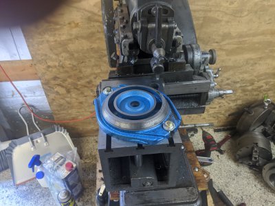
Which brings us to a different problem: mounting. The vise that came with my Ammco has two critical features: a central mounting post (goes through the table to a nut/washer combo on the underside of the table top), and a way so that it can easily be aligned to a 'normal' (jaws perpendicular to the ram travel) orientation via the central slot.

The keyway is easy; the mounting post, not so much. You might consider making your own graduated base which incorporates one. This is not as bad as it sounds: the base itself does not need to swivel, as the central post acts as the pivot. Of course this assumes the Atlas as the same style of vise mount - if it doesn't, then you'll need to come up with a mounting plate that can be indexed to common angles (you really don't need all 360 of them, right?) using the table mounting holes.

I don't know what class of work you are doing, but don't fret overmuch about the clearance. The stroke of the ram and the X-axis travel are much more limiting factors. You want the tool to be mounted as close to the end of the clapper as you can (unless you are doing dovetail or T-slot style work, in which case the point is moot), so tool stickout isn't an issue like with a mill. Remember also that you can replace the lantern on the clapper (or even the entire clapper) in order to support front- (not down-) facing tools. Workpieces that eat up the space between the vise and tool are probably too large to be held in the vise anyways. Don't neglect the sides of the table for mounting.

I've been doing a lot of work on my Ammco this week to get DROs mounted. Dunno if I'll start a thread on that, as I'm not really the photojournalist sort so my projects are not documented. I think there's already a shaper DRO thread.

One last thought for newly-christened shaperheads: track down the Ian Bradley books The Shaping Machine and Lathe And Shaper Tools. Slim volumes, aimed at the hobbyist size of shaper, lots of good ideas. You can usually find the books cheaper when they are written under his pen name, Duplex.
Huh... I never thought about just modifying the vise to mount using only a single bolt to rotate that way. Thats an interesting idea! There is going to be a negative for the mounting post in the bottom (since that is how the swivel bases work). On my mill, I do away with the keyway, the swivel base graduations are accurate enough to be within a thou across the jaws (which I fix when more accuracy is necessary). Part of the reason I liked the swivel base.

The atlas just has 3 T-slots, so I was originally going to use the 'wing' mounts, and perhaps keep the swivel base for swiveling (as well as just find a 'shorter' way to mount it).

That first Ian Bradley book is spendy! $100 is the cheapest I could find it! The second, even under the 'duplex' name still seems to be $65.
 
Not worth it. Wait a bit, the price will go down when nobody buys it at "w00t collectorz!!!!" prices. It isn't essential, and I think I overpaid at something close to fifty bucks with shipping
Abebooks has the tools book by duplex at about 15-20 bucks.

Ah, I see from lathes.co.uk that the Atlas table doesn't have a dedicated hole for the vise. That's unfortunate, it really knocks some height off the vise.
You can kinda see it here:
img4.jpg

There's even a matching hole on the side! (attribution)
 
One other thing that the pictures on the lathes.co.uk site reminded me of: you can get a lot of mileage from clamping a toolbit directly in the lantern, without using a toolholder. Look for a 3/8"x3/4" toolbit (3/8 is the maximum width the lantern on my Ammco can handle). Usually they are 6" long, so you can score one at 3" with a cutoff wheel or dremel, then snap it in a vise (cover with a shop rag if you value your eyes). Grind as usual, perhaps rounding the back since it will be striking the workpiece - with 3/4" depth to play with, don't worry, the tool will be stout enough.

These may be deep enough to recreate some of the forged shapes in the Bradley book, though I haven't tried yet. That's a lot of grinding. Hmmm.... carbide endmill?
 
Unpacking, examining:

Ok, first, this is worse than I thought it had any right to be. From a distance, it looks acceptable, but when I dug into it it was bad. It came with some mounting T-bolts and a set of ways 'keys'. However, the first problem I discovered; They lied about the height! I was accepting of the 2.7", but it turns out that is the VISE only, NOT including the rotary base! Everything included, the total height is about 3.910. You'll see how much of a problem that is later.

Here is everything included in the box (on my shop sweatshirt to protect my tablesaw top :) ).
IMG_20200617_142111.jpg

Pulled off the base, it looks pretty normal. There is a little bit of surface rust and some dings around, but nothing horrible. I WILL say that their grinding at least isn't too bad, it doesn't rock on the surface plate (none of the ground surfaces do).
IMG_20200617_142407.jpg

However, I immediately noticed something odd. The moving jaw actually doesn't seem 'centered'. It is flush in the 2nd picture, and short on the other. It turns out, the bed itself isn't even! It is an extra 50 thou wide on one side. Fortunately, it seems the 'extra' width is on the 'outside' based on some other measurements I made. High quality casting we've got here...

IMG_20200617_142541.jpgIMG_20200617_142547.jpg

I pulled a bit more off, the jaws came off easy enough, as well as the stationary jaw. There were 2 keys (not even centered), but at least they were tight.

IMG_20200617_143252.jpg

I found this part interesting on the back of the moving jaw. You'll see why this is as bad as it is later, but the 'relief' cuts for the corners look like they were done by a coke-head badger. You'll also note they did the little half-moon there and there is actually a casting defect in it.

IMG_20200617_143347.jpg


And the underside. Here is where I realized that NOTHING that isn't immediately visible is ground. There is just the horrible milled finish down here. Somehow they managed to do the relief cuts at a weird angle.

IMG_20200617_143432.jpg

The screw itself seems alright, I found the other washer for the thrust bearing after this.

IMG_20200617_143502.jpg

You can't really see it here, but the little half-ball is inside there. When I got this, it was stuck! It wouldn't move at all! The grease holding it in was so gritty that it wouldn't move at all. I ended up pulling it out, wiping it off, and using the rest as a ghetto lapping compound. it now moves only mostly terribly.

IMG_20200617_143549.jpg

Remember when I said nothing was ground that wasn't immediately visible? These are the jaw surfaces under the removable jaws. You can't tell very easily, but the fixed jaw actually has a pretty significant burr in this one from milling.

IMG_20200617_143629.jpg

In comparison, here is the 'outside' jaws, that are visible.

IMG_20200617_143634.jpg

I also noticed THIS. The nut itself is milled in a few places, but noticeably NOT where it interacts with the half-ball. This is likely on the 'to be fixed' list.

IMG_20200617_144745.jpg

AND here is the height problem. I've got the table all the way down and everything stacked up. It looks like it brings me down to only ~2" over the jaws with the tool in the highest position. ThinWoodsman suggested not using the tool holder, which will buy me extra space, but I likely want to get as much room as I can.

1 more interesting thing I'm reminded of from this picture: The base looks to have the degree markers 'laser etched', but there is no corresponding tick mark on the vise itself! You can see the little milled spot for it, but they never actually drew it in!

IMG_20200617_145433.jpg

Unfortunately the wings on this piece don't line up with the vise in this orientation. If I want to use it without the base, I will need to use it in the other orientation.

IMG_20200617_145516.jpg

The base itself is a touch too long to get into the T-slots. One step of this is likely going to be to shorten those wings a bunch, plus make the slots about 3/8" closer to the center on each side.

IMG_20200617_145554.jpg

I knocked out the pin and was interested to see that it is simply a piece of cold-roll that they didn't even bother machining to diameter. All my other bases (Kurt or nice clones) are at least machined (if not ground).
IMG_20200617_145937.jpg

I decided to knock out the ball-oiler at one point. This one was AWFUL. The ball would quickly get stuck ~1/2 way up, and it was super rough. I want to mill the top face down low enough that I think I'll get into this hole, and didn't want to hit it with the mill.

IMG_20200617_153331.jpg


All told, I think I can take about 3/4" off without much effort. I'm going to aim to get this down to ~3" if at all possible. I'm likely going to bring the removable jaws down from 0.945 to significantly less, I might aim for .750.

I will likely use it without the rotary base most of the time, but when doing internal fixtures on gears/etc, I obviously will need the rotary base to mount this at the other orientation.

Anyway, thoughts/feedback welcome! I'm not too concerned about ruining this, I only have about $70 into it so if I ruin it, I'm alright with that :) I'll likely be aggressive with my material removal as a result.
 
Looks like you've got your work cut out for ya!

You should track how many hours you put into it, divide by the cost of a Kurt or similar, and see what your time is worth. :)

I think someone else mentioned the idea of NOT using a tool holder, and instead mounting your ground HSS tool bit directly in the lantern holder. That'd give you an extra inch or two of headroom, by the looks of things.
 
Interesting build, it looks like there will be some serious whittling, to get that vise shaped object down to a workable size. I just went and looked at my Atlas 7B and the Altas shaper vise on it, there is a very noticeable difference in size.

After reading everyone’s comments, it appears, I’m the only person who seems to use the swivel base under the milling machine vise on a regular basis, to me its been a extreme benefit.
 
Is the base of the vise (without the swivel) larger than the table? You could mill out a table-sized pocket in the base, then find some way to mount it.

Or fabricate a tooling plate that mounts to the sides of the table (been sketching out ideas for one of these myself - U shape at table height, or rectangle with a picket milled out for the table, leaving maybe 1/4" over the table surface) to give yourself a larger surface to attach to - and with holed drilled precisely where they are needed.

It is longer, but narrower I think. I'm actually already considering removing the fixed-jaw-side 'drip tray so that I could potentially mount it closer to the machine.

I'm curious to see what your tooling plate looks like! I've been trying to think of a way to make a way of mounting with a rotary base too! Someone above mentioned that some shapers of this size use a center mounting hole. I am not particularly confident a single mounting bolt would keep this from spinning, otherwise I'd make a plate that has a mounting hole on all 4 corners into the table, then a center pin.
 
Day 2: Starting on the bases:

I decided to start on the body. I wanted to remove ~.200, so I started on the mill and tool off about .190 with a flycutter setup to do the full cut. The video/image of me cutting near the end is too big to upload. As a result of this cut, I lose the keys which kind of stinks but I wasn't particularly confident in them being straight anyway. Additionally, I'm going to have to get short head socket-head-cap-screws (or further counterbore!) since they now stick out the bottom. I probably want to do an Ace run for shorter ones once I hack apart the rest anyway, so I'm not too worried.
IMG_20200618_132911.jpg

I opted to surface grind this face before flipping to make sure I end up with a compounding error. The surface grinder is the most accurate machine in my shop, so I'll take advantage of that.

IMG_20200618_140900.jpg

Here is the bottom off the grinder. The finish ended up pretty bad, I think I did a poor job dressing the wheel this time and it ended up leaving a rough finish. BUT, it is flat, so I'm happy for now. Out of the ~2.7" for the vise, and 3.910" of total height, I've knocked almost exactly .200" off! My goal is sub-2" for the vise+jaws, and ~2.8" with the rotary base. We'll see how that works out :)

IMG_20200618_141226.jpg

I didn't have enough usable room next to my DX6, so I had to pull it and face off this. Again, I did this with a fly cutter. The 'rails' themselves are a about .520", and I aimed for .300". Spoilers: after grinding I hit it exactly!

MVIMG_20200618_143312.jpg

After fly cutting, I ended up with a really smooth finish. I DID lose the rear hump of the handle section as it is now smooth (don't worry about that thin webbing on the left, it is well supported by the iron all the way around). Losing that hump didn't matter, as the jaw couldn't get that far back anyway. I also lost the keys of the fixed jaw. I had about zero confidence that it was square to the rails anyway, so I'll have no problem re-cutting them accurately later.
IMG_20200618_144659.jpg

I then surface ground this side. It came out WAY better. At least the nice side is on the top. I DO have a red wheel I might try out at the end of this project if I want stuff to sparkle. I used a blue wheel recently and was very impressed with how shiny it ended up, so perhaps I'll do that too.

IMG_20200618_150016.jpg

For the rotary base, I considered cutting it on the mill. However, I found that my mounting bolts would get in the way, and I'd have a bunch of trouble getting the fly cutter moving around it. SO, I mounted it to the shaper table and went to town! I was hoping to get a little more than .100 thou out of this, and did quite a bit more!

IMG_20200618_164432.jpg

IMG_20200618_164434.jpg


I'm fortunate I gave up at this point! I have JUST the ends of the single-degree ticks left! I didn't mind too much, as I figured 90/45/60/30 are my most important anyway, but it would be nice to keep these. If they end up being TOO bad, I might see if I can get this on my rotary table and find a way to cut these instead of the laser writing.

IMG_20200618_170431.jpg

I didn't get a chance to grind this, as I got called in for dinner! All told, the progress is:

Main Body: Started: 1.830.
After milling the bottom: 1.650
After Grinding the bottom: 1.630
After milling the top: 1.410
After grinding the top: 1.407
Savings: .423"

Rotary Base: Started: 1.162
After shaping the top: 1.027
Savings (so far!): .135

For the base, I want to pick up another ~.200-.250 off the base to get to under .800 in height.

I'm planning on getting the jaws down quite small as well, they are currently ~.950, and I hope to have them at about .650 when I'm done. This should leave me at 2" for the main vise, plus an extra ~.800 for the rotary base.
 

Attachments

  • IMG_20200618_162556.jpg
    IMG_20200618_162556.jpg
    3.8 MB · Views: 12
I once did a cleanup/refurb on a similar Chinese mill vise that I bought used. The entire half-ball assembly was rough-cast on mine, too. Filed the flat area on the nut. Then, measuring the diameter of the ball, I wore down a Dremel cutoff wheel (#420 or 409) to as close to the same size as possible. Used that to smooth out the ball seat as best I could, kept checking it for smoothness with the tip of my finger. The vise works pretty well now.

I do occasionally wish I had a surface grinder. Ah, well ...
 
Back
Top