-
Welcome back Guest! Did you know you can mentor other members here at H-M? If not, please check out our Relaunch of Hobby Machinist Mentoring Program!
You are using an out of date browser. It may not display this or other websites correctly.
You should upgrade or use an alternative browser.
You should upgrade or use an alternative browser.
Treadmill Motor & it;s uses
- Thread starter Charley Davidson
- Start date
The board on the left is the motor speed controller, the board on the right is the controller for the incline. You would need both for what you want to do.
If I understand, you want the treadmill motor to run the drill and the incline to lift the table, right?
build a control pannel for a 5k ohm linear pot to replace the slider for motor speed, subsiytute switches for the incline controls on the console.
Chuck
If I understand, you want the treadmill motor to run the drill and the incline to lift the table, right?
build a control pannel for a 5k ohm linear pot to replace the slider for motor speed, subsiytute switches for the incline controls on the console.
Chuck
The 10K pot would probably work if it is linear taper as opposed to audio taper. I'd try it if I had it. Can't help much on the incline motor as it is AC and don't get along with that! Though it looks like I have the same motor, controller and incline motor from a Freecycle treadmill. The motor and cntrller are on my X2 mill and working great. The incline motor is under the bench gathering dust. I don't believe I saved the incline control board.
Chuck
Chuck
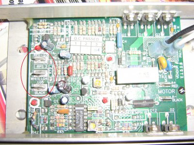
Where the origional control panel slider connects to the controller there are 3 connections, right? Should be marked H-W-L for High, Wiper, and Low. These correspond to the 3 connections on the pot. One outside is High, center is Wiper, and other outside is Low. If speed increases when pot is turned conter clockwise, reverse the H and L connections.
Chuck
Chuck
Looking at the motor controller only, is it marked MC-60? It looks identical to mine. I have disconnected everything from it and connected AC with a off-on switch, the motor, and the pot directly to just the motor controller board. If it is not a MC-60 controller, I may be misleading you.
Chuck
Chuck
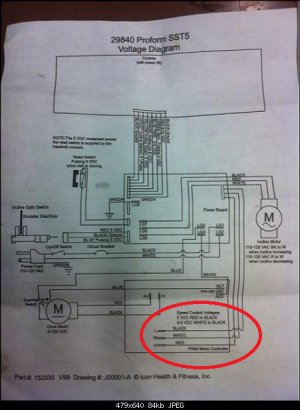
On your schematic you will see 3 wires running from the power board to the controller board. Circled in red. these are the wires you remove and replace with the pot. Red and black go to the outside terminals on the pot and white is the center, swap red and black to change the rotation of the pot.
Brian


Brian

There is no slider, there are 8 wires going from the power board to the control board labeled: Black Ground, Red 8-12vdc, Green Tach. Pulsing 5vdc, Blue PWM..0-5vdc, Orange Incline Up 5vdc, Yellow Incline Down 5vdc, Violet Incline Sensor 5v Pulse, Black Ground.
View attachment 54768
View attachment 54769
View attachment 54770

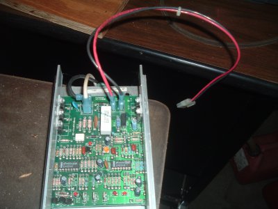
The attached picture is my spare MC-60 controller,

Top left is the AC in, with the treadmill circuit breaker in the black line. Top right is the motor connection, Red+, Black-. Wire in a double pole double throw center off switch to reverse the motor if necessary.
Botom of the board are three terminals marked H, W, and L . This is where you connect the pot. H to one outside terminal, W to cwnter terminal, and L to other outside terminal. If direction that the pot turns to increase/decrease speed of the motor is reversed, reverse the wires on H and L.
Is that clearer?
Chuck
edited to correct spelling


