Turning a flange mount motor into a flush mount?

Remove the 1/4" flange from the new motor?


  • Total voters
    1

mariner3302

Registered
Registered
Joined
Feb 27, 2015
Messages
105
Yes, I DO know that this probably isn't recommended! Please don't just say just that! I am looking for a REASON not to do it.

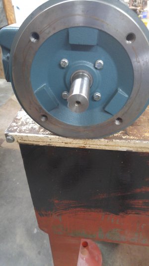
My Gorton 0-16A had a 2 speed (low - 1hp, high - 2hp), Waferthin motor but it was permanently wired for 440v 3 phase. I decided to go with a new motor and VFD since it cost less than the converter/transformer route.

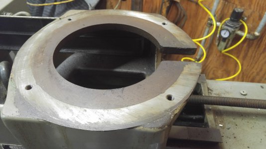
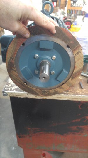
So... the new motor fits about half its mounting surface on the mill's motor mount. A side issue is that the shaft length is a little short. My thought is to take off the 1/4" flange by cutting or grinding it to a flat surface. That makes the motor's mounting surface effectively about 1/2 again bigger. If I do this, I am going to fashion clamps to secure the motor to the mill, using the original motors threaded holes.


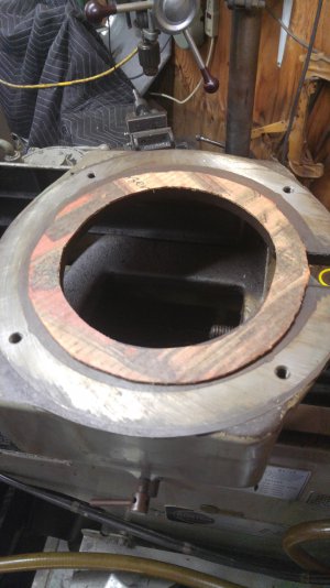
The other option is to cut a piece of steel to the size of the outer edge of the mill's motor mount with an inner hole for the shaft to go through. Then bolt that plate to the motor and to the motor. That will force me to extend the shaft.

That old motor is for sale, by the way.
 

Attachments

  • 2020-06-24 10.13.03.jpg
    2020-06-24 10.13.03.jpg
    2.1 MB · Views: 36
  • 2020-06-24 10.13.14.jpg
    2020-06-24 10.13.14.jpg
    5.6 MB · Views: 34
  • 2020-06-24 10.13.29.jpg
    2020-06-24 10.13.29.jpg
    2.1 MB · Views: 33
  • 2020-06-24 10.13.42.jpg
    2020-06-24 10.13.42.jpg
    2.3 MB · Views: 32
Personally I wouldn't cut down the motor, but rather make an adaptor plate. I would use a 1/2" or thicker plate. Mill or bore a hole the size of the mounting flange on the motor, and drill holes corresponding to the motor bolt pattern. Then drill another set of holes matching the mounting pattern of the old motor. The plate should be thick enough to counter sink or counterbore for either flat head or socket head bolts to the motor. If clearance allows I would use hex head bolts to fasten the motor/plate assembly to the mill.

Since you already need to extend the shaft I would make a one piece coupler/shaft. You can broach an internal keyway on the end that fits over the new motor shaft, and mill a keyway on the shaft end to correspond with the one in the mill

I have used this method on several motors from saws to grinders. It keeps the strength and integrity of both the motor and the mill and makes assembly or disassembly easy.
 
Yes, that is exactly the 2d option I mentioned. I will probably have to make the adapter anyway.
It looks like a lot of what I wrote initially above didnt come through.
The shaft is 1 1/8" and the pulley is 1" so I have to work on the shaft anyway. I am probably going to shave 1/16" off both the pulley and the motor shaft with the lathe.
Anyway, I figured to use 1/4" plate as you described to keep the weight down on the mount. The motor mount on the mill is over 1/2". Since the new motor has at least half its surface on it, I cant see how the motor will gain anymore rigidity at the expense of the weight. I have the 1/2" plate but would rather not use it. I have considered using 4 pieces of flat stock bolted to the motor and mill. I am certainly over-thinking this!
 
I would consider using a single piece of aluminum plate rather than steel. I think you're going to need at least 1/2" thickness to be able to have enough material left when counterboring or countersinking holes. Don't forget the standard height of the head of a 1/4" socket head bolt is 1/4". You'll need a thicker plate if you intend to use socket head bolts. The rule of thumb for socket head bolts is that the height of the head is equal to the diameter of the thread. The thickness of the head of a 1/4" flat head screw is .165". While it will work it only leaves .085" of material between the head and the motor.

I've used 6061 aluminum plate for this application both in an industrial and a hobby setting. With larger motors I've used plate up to 1 1/2" thick. There are currently several listings on eBay for 1/2"x12"x12" 6061 aluminum plate. Most run in the $50.00 range.
 
Last edited:
Although I appreciate the recommendations, which I do, what I am asking is what are the downsides of trimming the flange lip off the motor... Removing the 1/4" of lip will allow me to mount the motor directly to the mill's mount in the way the original motor does.
 
Although I appreciate the recommendations, which I do, what I am asking is what are the downsides of trimming the flange lip off the motor... Removing the 1/4" of lip will allow me to mount the motor directly to the mill's mount in the way the original motor does.

I'm afraid that's a question only the original designers could honestly answer unless someone has done it to a very similar motor. It seems like 1/4" wouldn't make that much of a difference but until you do it you won't really know.

However, I'm fairly certain that once you start trying to cut that thing you will wish you had the mill running with a rotary table. I'm still unclear on what you would actually gain by cutting the motor down since it sounds like you'll still end up with some kind of adapter for the shaft. if you got a really good deal on the motor and can afford to purchase another one should the plan fail then go ahead, otherwise I'd go with option two.

JMHO,

John
 
Although I appreciate the recommendations, which I do, what I am asking is what are the downsides of trimming the flange lip off the motor... Removing the 1/4" of lip will allow me to mount the motor directly to the mill's mount in the way the original motor does.
Maybe I'm not understanding what you intend to do. By saying you want to "trim the flange of the motor", I assume you mean you want to make the end cap thinner. If that's the case how thick will the end cap be when finished? Will it be thick enough to retain enough threads to secure it to the mill? Rule of thumb for threaded mounts is that the depth of the thread should be 1-1/2 times the diameter.

As matthewsx mentioned I think you're still going to need some type of plate between the motor and the mill. The bolt pattern on the motor looks like it will be barely catching the flange on the mill. I don't think clamping it in place will be sufficient to secure it against the starting forces of the motor or the resistance of the cutter in the work piece. Clamping it also will make it difficult for it to remain concentric with the shaft coupling.
 
Make a larger adapter plate between the motor and the head, counter sink the mounting bolts to the motor, you can use button head screws. Then drill holes through the plate to aligne with the old motor flange bolt. It may be possible to cut down the flange on the motor, depends on how thick it is and how you are going to do it, let alone pulling it off the motor. Seems like a lot more work and cast iron can be brittle.
 
Removing the flange by "cutting or grinding" sounds a bit sketchy: the best way to do it would be by chucking the housing
in a lathe and turning the flange off. If there's enough material left it could be done. But, you then have the problem of
drilling new holes in the modified motor flange and the top of the mill in such a way as to guarantee shaft alignment. Done
right, that suggest both parts being set up in a mill and indicated before drilling.
By comparison, an adapter sounds pretty straightforward.

I don't know if it's possible, but can a motor shop rewind your stock motor for 220V 3-phase? That would be the easiest solution
of all.
 
another suggestion is to make a thicker adapter plate , and make a 1"stub shaft extension for the motor
 
Back
Top