- Joined
- Dec 3, 2013
- Messages
- 1,844
I have a question for those of you who do or have done machine work as a career.
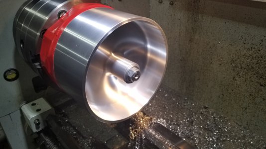
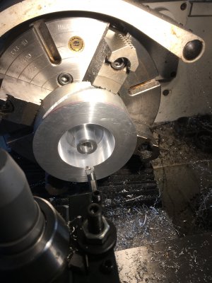
I'm working on a prototype part for a friend. It is an aluminum wheel 7" dia x 4" wide. All cross sections are .2" including the hub and central web. After squaring up the ends and rough turning the OD I bored the hub for the axle. The wheel will be spun up to 6k rpm so the final turning is being done on a precision ground mandrel so everything is as concentric as possible. The majority of the pocket material was removed on a CNC mill to within .05" for final turning on the lathe.
The trickiest part has been the internal fillets which are .25 radius. All I had on hand was some HSS tool blanks so I ground a form tool from a 1/2" square tool blank. With a 2" stick out I am getting a lot of chatter unless I plunge hard but that is difficult to control. Additionally when the tool bites into the material it pulls away from the backlash in the carriage even with some drag on the carriage lock.
My question are:
What tool would you use for the fillets?
Tips for controlling tool bite?
If all turning was done on a manual lathe, what tool would you use for roughing out the pockets?
Photo of the part with one side and final OD completed. The fillets are acceptable for a prototype for testing but not for a finished product. (FYI the red tape is helping contain 4 lbs of plumbers putty packed into the opposite cavity to dampen the harmonics otherwise the part was un-turntable.)


