Two Timer Build

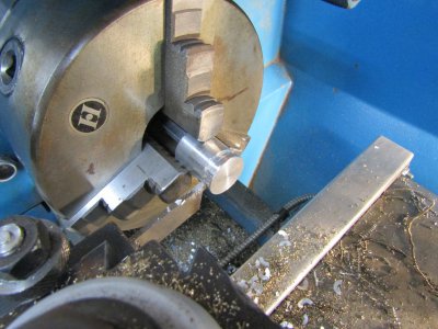
I made the valve spring retainers, cut the E clip grooves, and cut the valves to length.
Last night I spent 2 hours or so lapping the valves bu hand first with automotive valve grinding compound and then with some copper polish while watching the TV. The copper polish has worked very well for me in the past so fingers crossed. Time will tell if my work has been successful and the valves all seal.
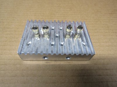
IMG_0219.JPG

Thanks for looking
Ray
 
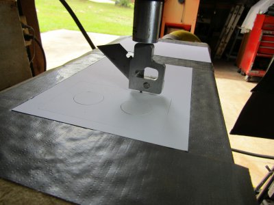
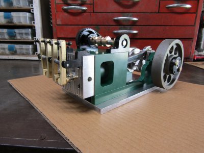
Not much for today I cut the o-ring grooves in the pistons and made some head gaskets.
IMG_0222.JPG
IMG_0226.JPG

I assembled the head to the engine to check if I had any compression. I am pleased to announce that my time in front of the TV set lapping the valves was well spent as both cylinders have good compression.

Thanks for looking

Ray
 
I am curious on how the valves will be actuated. Overhead cam?

Roger L
 
Hello Roger good to hear from you.

I have thought long and hard about the cam location and as I see it there are three possible locations. One between the engine block and the crankshaft, one on the engine block and one as an overhead cam configuration.
There isn't much room between the block and the crankshaft and the push rods would be quite long. It would also be close enough to the crank shaft to use cam gears but would probably need a set of three gears. That location is doable and would work well but I want to get away from timing gears.
An over head cam would be great if only for the "WOW" factor. The main problem I see is making a way to adjust the valve clearance. It would require me to scrap the current head and start over with a much more complicated design.
I think I have decided on mounting the cam on top of and at the rear of the engine block. It will use a timing belt and idler.

Thanks
Ray
 
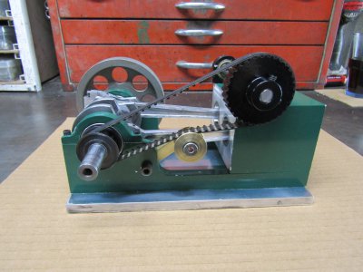
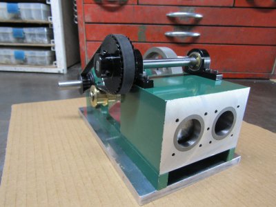
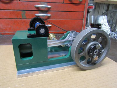
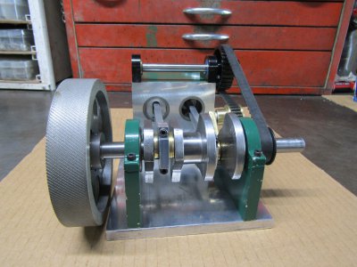
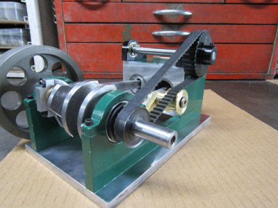
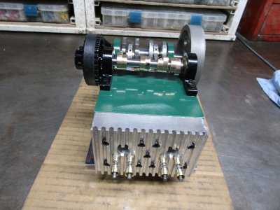
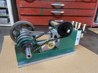
The cam is mounted on ball bearings toward the rear of the block and is belt driven.
The brass timing belt tension pulley is adjustable and rides on ball bearings as well.
The flywheel in the pictures is not the one I will use I just put it on so I could turn the crank.
A picture is worth a thousand words so here are 5 of them pictures not words.

IMG_0229.JPG
IMG_0233.JPG
IMG_0236.JPG
IMG_0239.JPG
IMG_0241.JPG

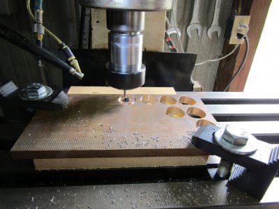
This shows how I cut the cam lobes. CNC is sure nice.
IMG_0242.JPG

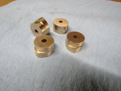
I didn't have any brass of the right thickness so these were made from bronze.
I still have to bore out the inside hole and then add set screws to the lobes.
Cam lift is 0.085
IMG_0248.JPG

Thanks for looking

Ray
 
Looks good. Like the fancy brass idler on the timing belt.
 
I drilled and reamed the cam center holes and installed the set screws.
Drilled and tapped the spark plug holes and put the head back on so I could determine the length and design of the rocker arms.
IMG_0253.JPG

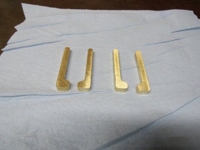
In order to give the spark plug wire boots enough room I had to offset the ends of the rocker arms.
This gives me about 0.725 between the intake and exhaust arms.
I roughed out four arms before I called it a day.
IMG_0250.JPG

Let me know what you think.

Thanks for looking
Ray
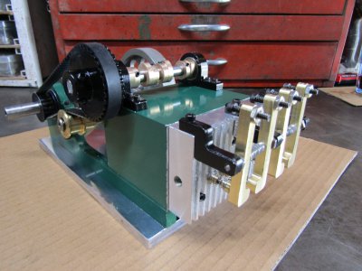
 
Drilled the center pivot point, and drilled and tapped the adjuster bolt holes for the rocker arms.
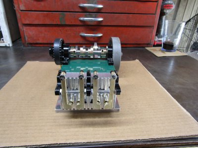
I made three rocker arm shaft stand offs and mounted them on the engine.
The arm shaft is 0.125 so I thought I should have three instead of two supports.
I put the springs between the arms to hold them in position but still have some play.
I know you like pictures so here are 4 of them.
IMG_0255.JPG
IMG_0259.JPG
IMG_0262.JPG
IMG_0265.JPG

Still no comments?

Thanks for looking
Ray
 
I am speechless...
R
 
Back
Top