Two Timer Build

The mower is mounted on my 1951 Allis Chalmers tractor and is just under 8 feet wide.
Here is the thread.

I will be working on both projects at the same time.
Ray
 
I had some time to day to get back to the Two timer.
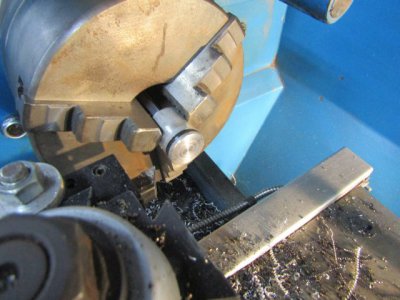
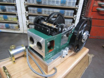
I reassembled most of the engine and checked my piston to deck height. After decking the cylinder head twice my compression ratio would be about 8 to 1 so I put the pistons in the lathe and shaved of 0.040. That will put me at 6.55 to 1 as I revised my thinking from the original ratio of 7 to 1. That should allow the engine to idle slower I hope.
IMG_0485.JPG

You can see the red gasket maker material in the engine block as I was not neat and tidy in it's application. I have confidence the water jacket will be water tight now.

IMG_0488.JPG

I am planing to make a valve test plate to ensure the valves are sealing properly. I have done this on the other engines I have built but this time I thought it wasn't necessary. Like I said before I want to recheck all aspects this time so there won't be any more surprises.

Thanks for looking

Ray
 
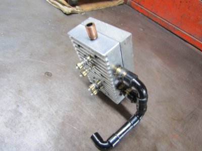
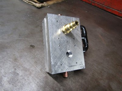
I made a test plate for the cylinder head to check the condition of the valves. I have done this on all my other engines and it makes it so easy to find any leaks. I attach an air hose to the back of the plate and listen for any air escaping. If there is a leak and you can't determine just where it is coming from then the whole assembly with the air hose attached can be submerged in a bucket of water. The bubbles show the spot but this time there were no leaks. I must be doing something right when I make my valves and valve cages.
IMG_0505.JPG

IMG_0504.JPG

Thanks for looking
Ray
 
Extra work making the test plate but it will be worth it when you put it all together. If you have any issues, you've eliminated the valves as the problem.
 
Many things got in the way of progress but the build is on the move again.

I'll bet you could machine a cool intake manifold that bolts on there. Maybe something V shaped?
That quote from rwm has had me thinking and the intake manifold I had built was kind of ugly and took up a lot of room so I came up with a new design.

IMG_0537.JPG

IMG_0538.JPG

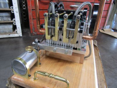
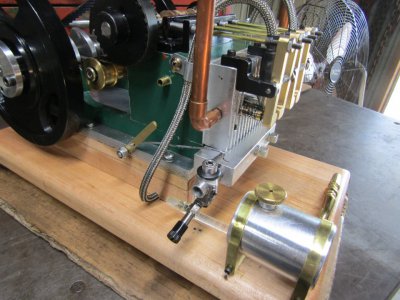
I used an aluminum plate that bolts to the bottom of the head with a gasket and holes drilled in it that line up with the intake ports. The 1/8" pipe plugs close the off the two holes I drilled to intersect the intake ports. The carburetor port was drilled the length to intersect the far pipe plug hole. It is not real fancy but it works fine and shortens the over all distance from the carb to the intake valves by almost two inches. I had to move the gas tank forward and flip it around to get enough room for the carb.

My good friend Chris has modified a couple of R/C carbs for me. He is trying to get the venturi size smaller to closer match these engines and not the 10,000 rpm they were designed for.
We have been doing some tests with them and so far we haven't had a total success but we are still looking at different approaches and haven't given up.
The carb on the engine now is a stock one that has worked fairly well for some of my other models.

I may have a video of the engine running in the next couple of days if things work out.

Thanks for looking
Ray
 
I think that looks great! I like it with the copper exhaust stacks.
 
OK I finally have one of the issues corrected and that one caused me the most problems. It ended up being the gas tank.
When I made the gas tank I used a sealant that was not compatible with gasoline. (my bad choice)
The tank didn't leak but the gas slowly dissolved the sealant into a transparent very fine scum that would plug up the carburetor and fuel line at slow speed. When the engine was running at high speed it could overcome the scum and act normally but run very rich. Needless to say it was very hard to start and when ever the throttle was reduced it would just quit. I will be going back and retest the other carb that Chris made for me but not right now.

The engine is not running exactly the way I want it but this is a big step forward. This build is not anywhere near complete as I have found the connecting rod bearings were not made to the right size and are knocking badly so that is what I will correct next. (another my bad)
We still have the cooling system to sort out and much more to do so keep watching.

Here is a video of the engine running today.
A hand held tachometer read 425rpms.


Thanks for looking
Ray
 
I'd be proud to get an engine running that good.

Greg
 
Thanks to all of you for the kind words.

On closer inspection of the connecting rod bearings I found the noise was coming from the rods slapping the crank throws. I had made the connecting rod bearings too narrow and they were rattling from side to side as the engine ran.
So how did I make a shim or spacer to fill in that extra side space?
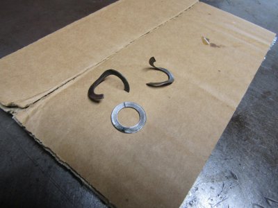
I chucked up a piece of mystery steel in the lathe and turned the outside down to 0.750 and drilled a 1/2" hole through the center. Using a cut off tool I made several thin washers about 0.020 thick. I then cut one side with a side cutter and bent them into a pretzel shape to fit over the crankshaft journal.
IMG_0542.JPG

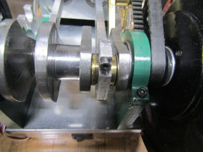
I them straightened them out as much as possible and installed the connecting rod.
You can see one of the shims on the right side of the connecting rod bearing.
IMG_0544.JPG

I had no idea if this would work. Maybe the shim would catch on something and end up being flung out in a twisted mess.
I am happy to say the shim stays in place and does not interfere with the rotation of the rod or crank.
I did this to both of rods and the noise has been greatly reduced.

Thanks for looking
Ray
 
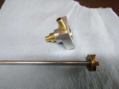
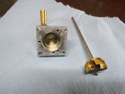
I am slowly getting the issues corrected and thought it was time to take another look at the cooling system. If you remember I tested it one other time and it did pump but the pump shaft leaked water very badly. I modified the pump and squeezed an oring between the two bearings but never tested it until now.
I temporarily hooked up the pump and tested for flow and leaks. I was very surprised at the large amount of water the pump moves after I had spacing the impeller a little further in to the housing. Even at close to idle the flow is impressive but the water leak at the shaft was still there. I decided that I needed to rethink the pump and come up with a way of sealing the shaft for good.
I eliminated the two bearings and added a brass bushing instead. The bushing has a 5/16" threads in about half of it's length and and the other half acts as a bearing for the shaft. In the thread end I have a bushing that screws in with an inside hole for the shaft.
I am hoping to make a stuffing box between the shaft and the adjustable bushing to be able to stop the water leak. There will be some type of string or graphite cord inside the box that will be compressed around the shaft as the smaller bushing is screwed in.
A stuffing box was used on many of the older pump and water faucets years ago.
I also had to make the shaft longer and will have to space the pump further away from the engine for clearance of the pulley.
IMG_0547.JPG
IMG_0549.JPG


Thanks for looking

Ray
 
Back
Top