Ultimate 3 phase converter

Karl_T

H-M Supporter - Sustaining Member
H-M Platinum Supporter
Joined
Oct 14, 2014
Messages
1,966
I will soon be helping my son build what I'll call the ultimate 3 phase converter. he has just built the ultimate shop for his life - a 30' x 40' super insulated building with in floor heat.

This will be the fifth rotary converter I've built over the last 25 years. There is a five year old post on the fourth one: https://www.hobby-machinist.com/threads/25hp-3pahse-conveter-with-load-center.26944/

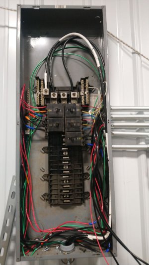
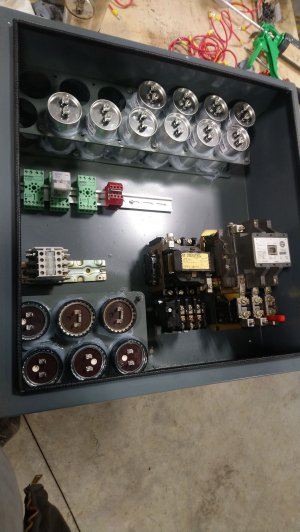
This unit will be similar to gen 4. Some features. It will use a 3 phase load center for all fusing. Each machine will have its own circuit breaker for this panel. In addition there are two idle motors, a 7.5 hp and 25 hp with each motor having its own circuit breaker.

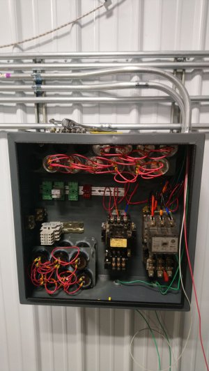
Both idler motors have a motor starter in the converter panel. Also plenty of both start capacitors and run capacitors. Timers will be used to bring in motor1 along with start caps for motor1 then drop the start caps and bring in run caps for motor1. Another timer will then bring in motor2 a few seconds later. finally run caps for motor2 a few more seconds after that.

The unit will be set up so he can just turn off the circuit breaker for motor2 when smaller 3 phase loads are used - not use the larger motor at all.

A push to start, push to stop buttons will be used to start and stop the unit.

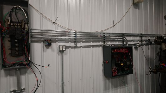
OK, today the kid just got the empty panel mounted. I told him get the power wiring done and then I'll come over and do the logic wiring and debug.converter box.jpg
 
Watching!

popcorn3.gif

Thanks for sharing your build!
-brino
 
I like the idea of 1 large motor and 1 small motor.
Cheers
Martin
 
Yep, my gen 3 had a large (15hp) and then a huge motor (25hp) . dims all the lights. Gen 4 had a 5 then a 20. here's a you tube - hardly can tell when it comes in.

smaller start motor is a great way to go if you need a large unit.
 
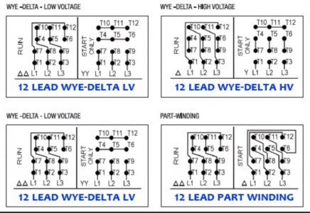
OK, first question from the kid. He's got a 12 lead 480 volt wired motor and found this:

12/1 Out

11/3 Out

10/2 out

7/4 capped

5/8 capped

6/9 capped

I found this info on line12 lead motor wiring.jpg
 
I think he has 12 lead wye hi voltage - 2nd from right top row.
He should wire it 12 lead wye low voltage - upper left in pic.

Correct???
 
I will soon be helping my son build what I'll call the ultimate 3 phase converter. he has just built the ultimate shop for his life - a 30' x 40' super insulated building with in floor heat.

This will be the fifth rotary converter I've built over the last 25 years. There is a five year old post on the fourth one: https://www.hobby-machinist.com/threads/25hp-3pahse-conveter-with-load-center.26944/

This unit will be similar to gen 4. Some features. It will use a 3 phase load center for all fusing. Each machine will have its own circuit breaker for this panel. In addition there are two idle motors, a 7.5 hp and 25 hp with each motor having its own circuit breaker.

Both idler motors have a motor starter in the converter panel. Also plenty of both start capacitors and run capacitors. Timers will be used to bring in motor1 along with start caps for motor1 then drop the start caps and bring in run caps for motor1. Another timer will then bring in motor2 a few seconds later. finally run caps for motor2 a few more seconds after that.

The unit will be set up so he can just turn off the circuit breaker for motor2 when smaller 3 phase loads are used - not use the larger motor at all.

A push to start, push to stop buttons will be used to start and stop the unit.

OK, today the kid just got the empty panel mounted. I told him get the power wiring done and then I'll come over and do the logic wiring and debug.View attachment 316644
nice,thought abt it, but 42 amps by law can be taken from switcboard here, so my lathe is 12hp, i'd gobble near 140, so i continue to get my jiuce from a Lincoln Vantage gen/welder,it gives good power but uses a fair bit od diesel, bringing 3ph in would be 5---7 k
 
BTW, a fella named Fitch Williams helped me tune my gen1 and gen2 converters back in '98. His write up is still the best I've seen on how to build and tune a rotary converter. I just re read it for the 20th time.

<EDIT> Here's another GREAT write up. put here for reference
 

Attachments

  • FitchWConverter.pdf
    2.1 MB · Views: 18
  • SINGLE to 3 PHASE CONVERTER.pdf
    166.4 KB · Views: 15
Last edited:
OK, plan "A" for Friday.

1. wire start/stop buttons to bring in motor1 contactor, a delay off timer, and a delay on timer.

2. wire delay off timer to close small contactor for start caps. This contactor should stay closed for about 1 second after pushing "start" button.

3. wire small contactor in 2) to two each 300 MFD start caps between L1 and the "wild" leg on L2. Documentation indicates 50 -100 MFD start caps per horsepower. NOTE the start caps are all wired so its super easy to add or remove one during tuning - just pull a spade connector on or off.

4. Wire about 200 MFD of run caps between T1 and T2 (wild leg) on motor1 contactor. Wire about 150 MFD of run caps between T2 (wild leg) and T3. SAME NOTE caps are all wired so it is super easy to add or remove with spade connectors.

5. wire delay on timer2 to motor2 contactor. Set it to about 5 seconds delay before bringing in motor2


6. We will try to bring in motor2 without start caps. If this is a problem, a third delay off timer will be needed to again bring in the start cap contactor for a second.


7. . Wire about 200 MFD of run caps between T1 and T2 (wild leg) on motor2 contactor. Wire about 150 MFD of run caps between T2 (wild leg) and T3. SAME NOTE caps are all wired so it is super easy to add or remove with spade connectors.


8. need voltmeters to watch things as we debug.
 
Back
Top