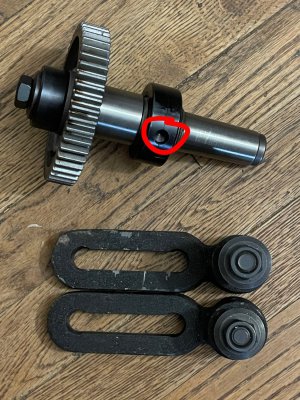
UNIVERSAL DIVIDING HEAD BS-2 PARTS

Looks like a Brown & Sharpe #9 taper?

Length of 2.156 x .0147/inch taper = .0899 difference in diameter

Small end .980 + .0899 = 1.0699

Pretty darn close to my measurements

And I think BS9 was the standard taper for the originals correct?

DD1D7F00-83AB-45F5-9DC1-1CCAA95F9D3F.jpeg
 
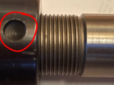
I guess the “square” thread is actually Acme…

Here are some pictures with the arbor torn down

18A1B3C3-AB52-4A5B-BD37-6AA4C78093BA.jpegF29BE138-5E83-4141-9602-23B6FDCD5DAD.jpeg
 
@Mill Lee farm ,I only see greate artistry in you scetches. Thank you so much for taking time to do so. This will help a whole lot more than just the pictures of the parts.

I was wondering, where is this pin used?
1678529688922.png

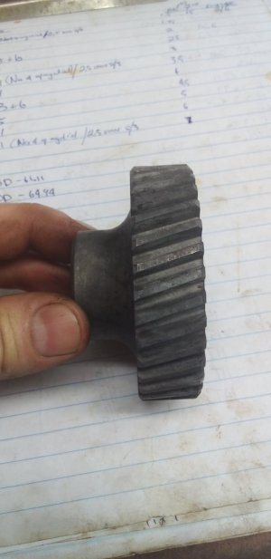
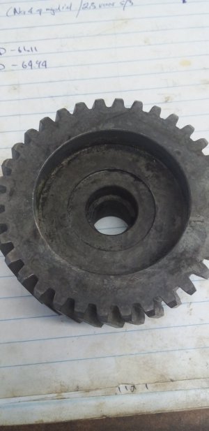
I gather that the diamentions your DH and mine are imperial,therefore the gears are also imperial. I need to make some missing gears too,24T,28T,32T,38T and 44T. So from what I calculated I must get DP12 14.5°PA gear cutters, although a Module 2 cutter I have fits pretty close in the profile. But I measured the PA using I formula I got somewhere on this site and it calulated to 14.5°. Adding to that,it does not make sense to have a module pith in metric if everything else like the gear bore is imperial.

Once again thank you for your help and time. Now I must get the cutters I am sorcing on Aliexpress and also comparing on ebay and then start making gears and parts. I am doing all this just to get a job from a potential customer who wants helical gears fom time to time like the pictures below.
20230215_100205.jpg

20230215_100219.jpg

These will be my first helical gear. Whish me luck.
 
I need to make some missing gears too,24T,28T,32T,38T and 44T.

@Suzuki4evr
Hi Michael,

You might consider 3D-printed gears here. Many people worry about their strength, but i) some new lathes come with at least one plastic gear as a sort of "crash fuse", and ii) you just need indexing, your use on the divider will likely never see even cutting forces if you manually set the position then lock the brake, make your cut, unlock, step, lock and cut, etc. (Unless, of course, you are generating the gears with a hob under power.)

Two offers:
1) If you can find a 3D printing service locally I could generate the STL model files on Fusion-360 and send them to you.

2) I could print you a set of plastic gears and mail them to you.

Either option at no cost to you!

If you're interested just let me know your final specifications (DP or mod, tooth count, gear thickness, bore dia., pressure-angle)

Brian
 
Two offers:
1) If you can find a 3D printing service locally I could generate the STL model files on Fusion-360 and send them to you.

2) I could print you a set of plastic gears and mail them to you.
GEEEEES Brian,what a generous offer. I will cirtainly try to find out if there is a 3D printing service near by. Your other offer sounds amazing,but I think the shipping will be a killer to South Africa. How much do you think shipping would be to Wellington South Africa?

As soon as I can I will work out the diamentions, I must do it anyway.

Man what an offer....Thank you Brian.
 
Michael,

The cost of production here will be ridiculously low... see this post for my costs on 3D gear making:
https://www.hobby-machinist.com/threads/erichs-benchtop-gear-hobber-project.101649/post-997049
Fusion-360 has a gear generator where I just need to input the specs and out pops the model file.
The printer is sitting here waiting for a job, and I have spools of filament that I buy when they have a good sale.
All your gears will cost less than a cup of coffee.

I currently have no idea about shipping cost to you, however the weight will be very low, no insurance required because it would only cost a couple dollars to replace them. I wonder if it would be cheaper to send them one at a time in envelopes, rather than one larger "package". I will look into it; a stop at the post office should give me some guidance.

Besides, I'd like help out and see your project continue.
This is really a learning exercise for both of us on materials and suitability of 3D printer plastic gears for the purpose.
You would be on the hook for some honest feedback about accuracy, usability, wear, etc.

Brian
 
Wow @brino ! That’s a fantastic offer! Karma points to you sir! :D

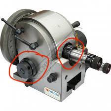
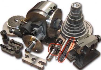
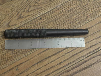
@Suzuki4evr the pin is dead simple and used as a lever/wrench to turn both the arbor ring (with the acme thread) and on the side of the head itself.
Just make a pin that fits the socket on your dividing head. I can take a measurement later if you really need it.
(I’m not home so I had to steal images from the internet instead of just ‘taking’ photos lol)

52DA89D6-750A-4C0C-9A8A-AC9963386D7F.jpegC77EC14E-6A80-4381-9FDD-C5B8A1EE1FBF.jpeg

C17926FD-C2E1-4781-AEF1-291479C11E79.jpegCEC32E2C-0A96-46CC-893F-61E85791C382.jpeg
 
Yes as soon as I posted I realized what it was for,but thank you for your reply and pics. When you have time,can you perhaps confirm the gear profile is DP12 14,5°PA and not M2 20°PA?
 
Back
Top