Upgrading My PM 1236-T Lathe

wildo

Registered
Registered
Joined
Dec 7, 2015
Messages
519
Well I wasn't really planning on creating an entirely new thread on this, but I might as well. It all started when I uncrated the lathe and realized I just can't stand the white color. I asked on here, and did you guys ever deliver! You see, I had planned a one-shot oiler as well as a drag-chain DRO install. I'm also converting to VFD drive on 3 Phase. Someone linked me to David Best's amazing lathe build thread on Flickr and I couldn't believe what I was seeing. Not only did he already do all of the upgrades I was planning, but he also fully documented them and had plenty of other cool ideas as well. So yeah, I'm basically just copying his lead. I doubt you'll find anything new here that you didn't see in his build.

I started with the paint. I am using the Steel-It paint he used (I'm using both primer and base coat of the same brand). That plus the paint stripper (EZ Strip) and drop cloths arrived today. I also ordered a drag chain from Igus (118-048-063-0) which arrived today as well. And finally, I ordered a LOT of aluminum pieces to work on mounting all this stuff up. I'll pick up the aluminum cuts tomorrow.

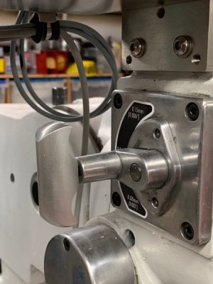
Tonight I started on the gearbox drip oiler. As I said, I intended to do a one-shot oiler anyway and I really liked David's implementation on this part. I actually ordered two oilers- one will hold gear oil for the gearbox, and the other will hold way oil to feed the cross slide (a la Keith Fenner's Rutland build). I got the shape profiled and it fits well. Tomorrow I'll drill the oil galleries.


IMG_9934.JPG


IMG_9935.JPG


IMG_9936.JPG


IMG_9938.JPG


IMG_9939.JPG
 
I will say- this is the kind of thing that I'd like to learn more about with machining. Since my Burke Millrite doesn't have the head nod, I could not for the life of me figure out how to mill the angle on the front of the aluminum plate. I came up with this rather sketchy setup with two dowel pins to support the work, and then toe clamps kind of holding everything in place. I climb milled only so that the tool pressure would be into the dowel pins. It wasn't until after I completed that I realized I could have taken the moving jaw face off of my Kurt 5" anglock and moved it to the rear, creating a vise span far long enough to hold the part. Then I could have tilted the mill head sideways. But it simply didn't occur to me at the time. This is the sort of thing I want to get better at.

IMG_9927.JPG


IMG_9928.JPG


Another thing I discovered that I don't have a clue about is how to chamfer round a corner. David's part looks totally amazing. His chamfer follows the curve perfectly. I thought that because I used a 1/2" ball nose end mill to create the corner, then using a 1/2" 100* chamfer mill would create a perfect chamfered corner. Yes- I can hear you all laughing from here. Naturally I was NOT cutting on the 1/2" diameter of the chamfer mill, and even if I was that still wouldn't have created the nice corner like David's. I don't know how to properly perform this operation.

IMG_9940.jpg
 
Willy, I really enjoyed your posts on this. Great work. I'm inspired to share some thougths now that you're in the deep end of the swimming pool. LOL

Your angled face milling setup looks fine. But for future reference, here's how I often machine angled edges on the mill. Since I'm primarily a woodworker and have very precise equipment in that sphere, I take a chunk of squared-up wood, go to the sliding table tilting arbor saw, set the blade to the right angle, and split the wood. I then use this wood gizmo as a clamping aid in the vise for the material to machine - like this:

292909


Drilling the galleries in the rather long oil distribution plate was a bit perplexing. On my mill at the time (RF45 - yes, the real deal, not a clone), with limited Z, I had a challenging time drilling the galleries in that oil distribution plate, but this is how I got it done - aircraft bits were just barely long enough for the main line. I started the hole with a jobber bit as shown below, then took the plate off the mill and continued drilling with the aircraft bit in a handheld drill on the bench:

292911


The ball-end corner you find challenging I sent off to Stefan Gotteswinter in Germany, he didn't know how to do it either, so he sent it to Robin Renzetti. Robin then referred it to Tom Lipton and he took it to Lawrence Berkeley Labs and they did some kind of particle accelerator treatment. LOL Just kidding. So first cut a half-deep trough with a square end mill, then plunged the ball end mill into each corner to full depth (running the tool very slow RPM to prevent chatter), then cut the remainder of the trough with the ball end mill moving the XY table, progressing down in 3 steps with the ball end mill.

If I were doing this oil distribution plate again, I think I’d put a slightly larger drip hole at the end of the line of galleries (above the feed shaft bearing) so that the priming of the plate takes less time and there is more oil distributed to the end point than along the gear train. It’s the end point that needs the oil the most because of that feed shaft bearing.

Keep posting. I'm really looking forward to seeing your progress.
 
The ball-end corner you find challenging I sent off to Stefan Gotteswinter in Germany, he didn't know how to do it either, so he sent it to Robin Renzetti. Robin then referred it to Tom Lipton and he took it to Lawrence Berkeley Labs and they did some kind of particle accelerator treatment. LOL

Ok- this made me laugh out loud! Hilarious!! That's definitely all the right names! hahaha!!


Great idea about using wood for fixturing; I'll remember that! Regarding the other part, I was actually referring to the smooth external radius on the top surface. I was able to use a ball end mill to get the inside radius at the bottom of the trough part- no problem.

[EDIT]- thinking about it more and considering you are big into woodworking, I'd almost guess you used a router & router bit to get that round over since it's just aluminum. Hmmmm....

radius.png
 
Ah, I misunderstood. Indeed, that was done on the mill using a carbide router bit with guide bearing. This kind of thing, although solid carbide - probably 3/8" radius on 1/2" shank:

292978


A have had really good results using carbide router bits cutting aluminum on the lathe as a form tool, so I decided to try it on this oil distribution plate. Example on lathe:

292979


Finished result for that part:

292981


I'm very much looking forward to following your project. Keep posting please.
 

Attachments

  • IMG_1537.jpg
    IMG_1537.jpg
    46.3 KB · Views: 261
Alright! Wrapped up this part of the project. To line up the oil drip ports, I blued the bottom of the plate and then scratched the locations through the gearbox with a piece of 1/16" rod bent to 90* in order to reach up in there. The oil galleries weren't really all that bad to drill. A while back I picked up this extra long drill bit set which made the hole a breeze. I went with 3/16" galleries throughout, with 1.5mm oil drips for most of the gear train, and 2mm oil drips at the back of the line above the feed shaft bearing. The part was clamped to an angle plate and the mill table taken nearly all the way down. Like David, I started the hole with a standard jobber drill bit, and then carefully finished with a hand drill using the long bit. The ends of the galleries were threaded and Loctite 272 was used- not for the high temp characteristic, but rather because it's more viscous than standard 271 and I thought that would help with thread sealing (which both formulas will do). It is also tolerant of machine oil.

IMG_9942.JPG


IMG_9943.JPG


IMG_9944.JPG


The long drill bit came within 1/4" of the end of the plate when drilled to the last flute.
IMG_9945.JPG


...And so that's exactly what I did.
IMG_9946.JPG


IMG_9947.JPG


IMG_9950.JPG


There was one oil spot that was a bit tricky to get to. I extended the oil gallery beside it, and then drilled at an angle to pick it up.
IMG_9951.JPG


IMG_9956.JPG


Galleries are blocked with 1/4 - 20 x 3/8" grub screws
IMG_9958.JPG


I don't yet have a 1/8" NPT tap, so this street elbow will go in once I order one.
IMG_9959.JPG
 
I haven’t had a lot of shop time lately, but I did take possession of all the metal bits I needed for the accessories being mounted.

293274
 
I did find some time not so much in the shop, but out in the garage today. I'm trying to tackle the projects that will need to be painted along with the lathe so that I can do all the painting at once. This gearbox oil pan was a cool idea; even my SB 9a drips a ton of oil out of the gearbox. (I suspect they all do since the bottom of the gearbox is open for the tumblers.) Fun little welding project...

293277


293278


293279


293280


293281


293282


293283


293284
 
Back
Top