Upgrading The South Bend 9 Cross Slide to Large Dial

Mark_f

Registered
Registered
Joined
Jan 16, 2020
Messages
5
Recently I upgraded my South Bend 9 lathe compound to a large dial. Now I am doing the cross slide. It is quite a bit different in design from the compound. I will be basing this upgrade on the procedure by Steve Wells and Ed Godwyn. However I am changing a few dimensions to suit my needs better. These upgrades are not too difficult and actually very forgiving. There are only a few dimensions that are critical. As with the compound, I will be making everything new so I can use the lathe by leaving the original assembly in tact until done.

I started by ordering some needed parts.
20170701_165656_HDR_resized.jpg
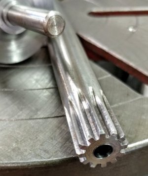
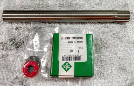
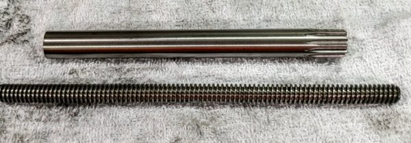
I ordered a new spline gear shaft from Steve Wells. This is a longer shaft than the original. I also ordered the thrust bearings. They were ordered from MSC as they were the only supplier that had the proper size bearings. The bearings are .375" ID and 11/16" OD. ( other suppliers had the bearing but with a 13/16" OD and this is too large). The 11/16" OD is necessary to match the gear shaft diameter.
20170701_165919_HDR_resized.jpg
I also got a piece of 7/16-10 LH lead screw to make the new screw with. ( Thank you to "jocat54" for supplying this for me.)

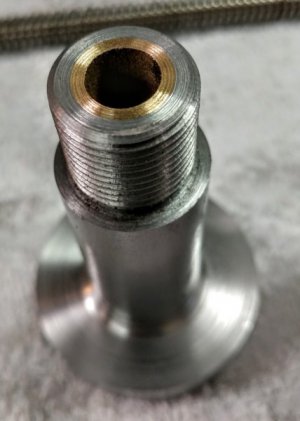
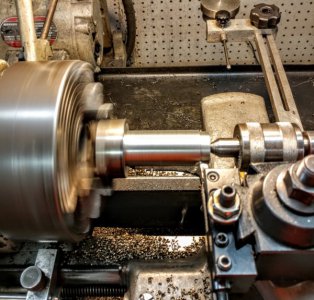
Next is to begin making the large bushing. It will be 2" diameter and longer than the original.
20170701_165604_HDR_resized.jpg
Machining the bushing shank down to .930" diameter the same diameter as the original)
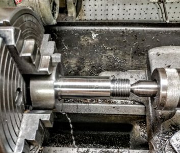
20170702_115846_HDR_resized.jpg
The first operation is complete and the 3/4-16 threads are put on while in this setup to be sure everything is concentric. Next the part will be turned around and put in a 15/16" ER 40 collet To do the boring, reaming and machining the bearing pocket and OD. This will insure that everything will be concentric (which is very important) as the ER collet is less than .001" TIR.
Parts Layout.jpg
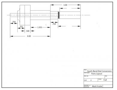
This is a parts layout diagram to be sure I maintain the proper dimensions. There are some dimensions missing which will be established and filled in as I go. I already made the graduated dial ( when I made the article about making these dials) and some dimensions are dependent on the actual dimensions of the dial.


This drawing is the large bushing.
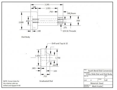
Cross Slide Dial and Dial Body.jpg
 
Last edited by a moderator:
One difference between Steve's setup and mine is the bronze bearings.
20170702_150500_HDR_resized.jpg 20170702_150507_HDR_resized.jpg
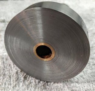
The shaft is .375" diameter, so I reamed the bushing through at .500" and pressed a oilite bushing in each end about 5/8" long and then ran a .375 reamer through them both. A piece of .375 drill rod "floats" nicely in the bushing. It was a little more work but worth the results. The bushing is over 3" long and I did not want the friction of the shaft in a hole that long. This reduces drag and friction greatly. Now I will cut the bearing pocket and polish the face of the bushing where the dial will contact it.

I used the large dial on the compound when threading the bushing and it was wonderful. when this one is done, the lathe will be a dream to use.
 
Last edited by a moderator:
All the parts are made. Next will be the fittings of the bearings and pinning the lead screw to the assembly.

20170703_112646_HDR_resized.jpg
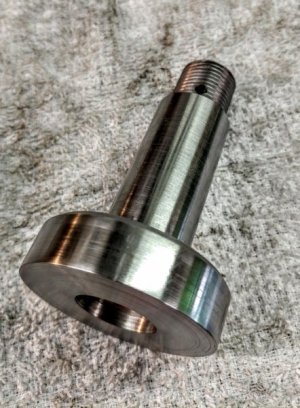
The oil hole was drilled, the bearing pocket is cut to a depth that should provide .002" of bearing preload. It is hard to see in the photo, but the zero line is scribed at the top. This piece was test fit in the cross slide, tightened and the spanner wrench hole and scribe line positions were marked.

20170703_180733_HDR_resized.jpg
This is the assembly waiting to have the bearings fit after the gear shaft is machined.

20170703_180750_HDR_resized.jpg
The gear shaft has been drilled and reamed .250" , 1 1/2" deep. Next will be to machine most of this 11/16" diameter shaft to .375" and the lead screw will be inserted with Lok-Tite and pinned.
 
One difference between Steve's setup and mine is the bronze bearings.
View attachment 236758 View attachment 236759
The shaft is .375" diameter, so I reamed the bushing through at .500" and pressed a oilite bushing in each end about 5/8" long and then ran a .375 reamer through them both. A piece of .375 drill rod "floats" nicely in the bushing. It was a little more work but worth the results. The bushing is over 3" long and I did not want the friction of the shaft in a hole that long. This reduces drag and friction greatly. Now I will cut the bearing pocket and polish the face of the bushing where the dial will contact it.

I used the large dial on the compound when threading the bushing and it was wonderful. when this one is done, the lathe will be a dream to use.
Mark I was wondering , would needle bearings work as well or worse. I've been thinking of using some in builds I'd like to do. I know the brass will be constant contact but thinking the needle bearings would be less likely to bind ever.
 
Mark I was wondering , would needle bearings work as well or worse. I've been thinking of using some in builds I'd like to do. I know the brass will be constant contact but thinking the needle bearings would be less likely to bind ever.

I suppose you could , but I doubt you notice any real difference. The Oil-lite bushings are only about a 1/2" long when finished so there is not much contact. I used Oil-lite bushing , not brass because they lubricate themselves to a certain extent. I put a .375 shaft through the assembly and it could not be any easier to rotate. The original design called for a reamed hole through the bushing , but I saw where someone else used bushings in the ends and the said it was so much better ( they had to put a lock on the cross slide to keep it from moving when cutting).

Needle bearings are great but not in all settings. I just feel it would be overkill in this one and maybe not as good as the bushings
 
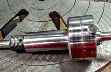
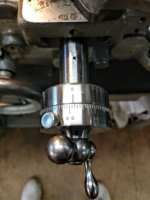
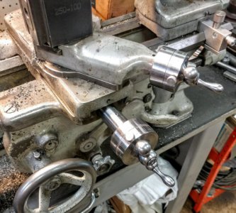
I finished the large dial for the cross slide. I did the final fitting of the bearings and assembled the unit. the following two pictures are of the new assembly installed.
20170706_161235_HDR_resized.jpg
20170706_161239_HDR_resized.jpg
I am very happy with the results and would advise anyone to do this modification. it is so much nicer.

There is one issue that bothers me about this procedure. the small busing that the dial sets on is locked to the shaft by "clamping it between the thrust bearing and the crank handle to keep it from turning free. by putting enough pressure on the bushing to lock it tightly , it also puts too much pressure on the thrust bearing making it turn harder. It is a fine adjustment and if the bearing is lightly preloaded, the dial can be turned even when locked. This can be a problem. I have it working ok right now, but I don't know how long it will hold. I am thinking about a way to permanently fix this issue, but don't have it worked out yet.

All in all, these large dials are wonderful and so easy to read.
 
I am considering a compound bearing installation on my 10" Atlas.
Did some searching and found this thread.

I am confused by the first image and your text regarding the thrust bearing.
I looked up the INA TC815 bearing in the picture and is shows as a 1/2' ID x 15/16" needle thrust but the pic shows a ball style.
Your text talks about a 3/8" x 0.688" thrust. I did some alternate searching and found a Boston Gear BALL thrust bearing with those dimensions.

In your pic, are we looking at two bearings or the contents removed from the box of one bearing?
You are talking about two different bearings. One is a 1/2"X15/16" needle bearing and the other is a 3/8"X11/16" ball thrust bearing.
I failed to mention the needle bearing for the front because there was nothing special about it. The ball thrust bearing was an odd one ( at least for my application ).
 
Back
Top